![]()
PWM Generation
This example shows how to use the PWM peripheral to generate 3-phase PWM signals with dead time.
Description
This example shows how to configure the PWM to generate synchronous 3-phase PWM signals with dead time (used for motor control). The duty cycle of the PWM is updated in the interrupt handler.
Downloading and building the application
To clone or download this application from Github, go to the main page of this repository and then click Clone button to clone this repository or download as zip file. This content can also be downloaded using content manager by following these instructions.
Path of the application within the repository is apps/pwm/pwm_synchronous_channels/firmware .
To build the application, refer to the following table and open the project using its IDE.
| Project Name | Description |
|---|---|
| sam_rh71_ek.X | MPLABX project for SAM RH71 Evaluation Kit |
Setting up the hardware
The following table shows the target hardware for the application projects.
| Project Name | Board |
|---|---|
| sam_rh71_ek.X | SAM RH71 Evaluation Kit |
Setting up SAM RH71 Evaluation Kit
- Connect the debugger probe to J33
Running the Application
- Build and Program the application using their respective IDEs
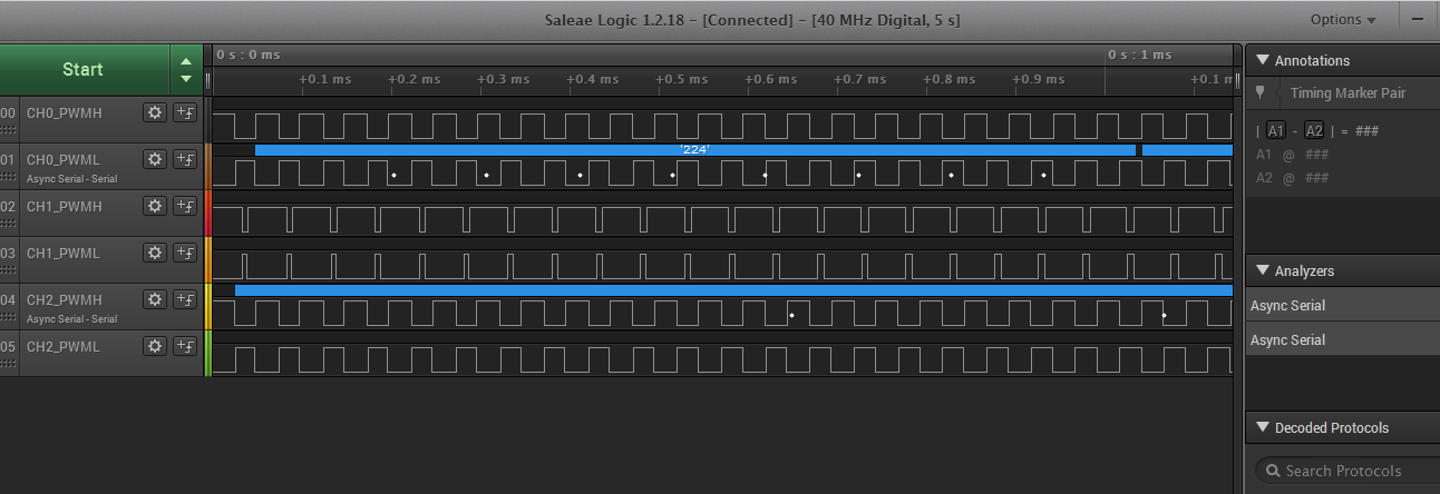
- Observe the high-side and low-side PWM waveforms on the oscilloscope
-
Observe the dead time between the high side and low side
Refer to the below table for PWM output pins for different boards:
| PWM Channel | SAM RH71 Evaluation Kit |
|---|---|
| CH0_PWMH | PA00 (Pin 7 of J24 ) |
| CH0_PWML | PA04 (Pin 8 of J24 ) |
| CH1_PWMH | PA01 (Pin 9 of J24 ) |
| CH1_PWML | PA05 (Pin 6 of J24 ) |
| CH2_PWMH | PA02 (Pin 16 of J24) |
| CH2_PWML | PA06 (Pin 17 of J24) |