![]()
TCC PWM generation
This example application shows how to use the TCC to generate a 2 or 3 phase PWM signals for motor control with dead time.
Description
TCC module is configured to generate synchronous 2 or 3 phase PWM signals with dead time. The duty cycle of the PWM signals is updated in the period interrupt handler.
Downloading and building the application
To clone or download this application from Github, go to the main page of this repository and then click Clone button to clone this repository or download as zip file. This content can also be downloaded using content manager by following these instructions.
Path of the application within the repository is apps/tcc/tcc_synchronous_pwm_channels/firmware .
To build the application, refer to the following table and open the project using its IDE.
| Project Name | Description |
|---|---|
| sam_l22_xpro.X | MPLABX project for SAM L22 Xplained Pro Evaluation Kit |
Setting up the hardware
The following table shows the target hardware for the application projects.
| Project Name | Board |
|---|---|
| sam_l22_xpro.X | SAM L22 Xplained Pro Evaluation Kit |
Setting up SAM L22 Xplained Pro Evaluation Kit
- Connect the Debug USB port on the board to the computer using a micro USB cable
Running the Application
- Build and Program the application using its IDE
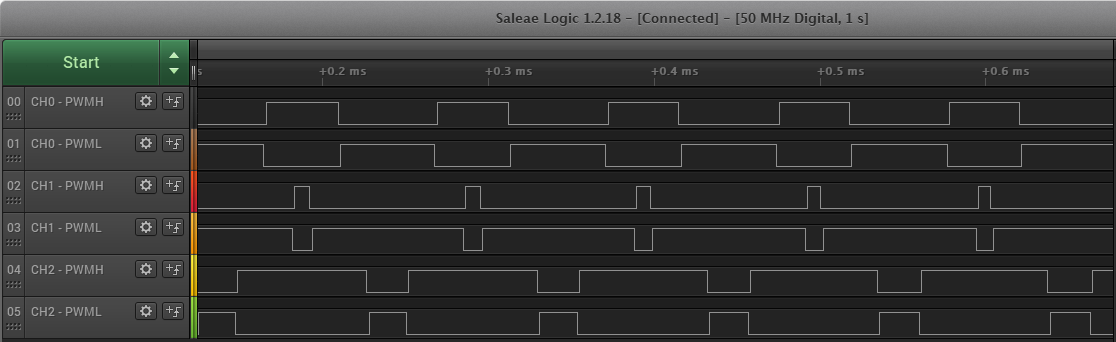
- Observe the high-side and low-side PWM waveforms on oscilloscope
- Observe the dead time between the high side and the low side
- Observe the pwm frequency to be 10 KHz
SAM L22 Xplained Pro Evaluation Kit pin details:
| Signal Name | Pad | Pin |
|---|---|---|
| CH0-PWMH | PB30 | Pin 11 of EXT1 connector |
| CH0-PWML | PC28 | Pin 7 of EXT2 connector |
| CH1-PWMH | PB31 | Pin 12 of EXT1 connector |
| CH1-PWML | PA23 | Pin 13 of EXT1 connector |
| CH2-PWMH | PA18 | Pin 16 of EXT2 connector |
| CH2-PWML | PA20 | Pin 5 of EXT1 connector |
SAM L22 Xplained Pro Evaluation Kit waveforms: