![]()
CCL Manchester Encoder
This example application shows how to use the CCL peripheral library and generate a Manchester-encoded output.
Description
This demonstrates a way to generate a Manchester-encoded output using a SPI port and the CCL. The SPI port is sending out a predefined buffer of data in a circular fashion. Data is sent out LSB first, with CCL_OUT being the Manchester-encoded output. Pins are configured such that a logic analyzer can be attached to see the input (MOSI and SCK) and the output (CCL_OUT) simultaneously.
Downloading and building the application
To clone or download this application from Github, go to the main page of this repository and then click Clone button to clone this repository or download as zip file. This content can also be downloaded using content manager by following these instructions.
Path of the application within the repository is apps/ccl/manchester_encoder/firmware .
To build the application, refer to the following table and open the project using its IDE.
| Project Name | Description |
|---|---|
| sam_l22_xpro.X | MPLABX project for SAM L22 Xplained Pro Evaluation Kit |
Setting up the hardware
The following table shows the target hardware for the application projects.
| Project Name | Board |
|---|---|
| sam_l22_xpro.X | SAM L22 Xplained Pro Evaluation Kit |
Setting up SAM L22 Xplained Pro Evaluation Kit
- Use jumper from PA09 (EXT3 pin 15) to PA18 (EXT2 pin 16). This routes SCK to CCL_IN[2]
- Use jumper wire from PA08 (EXT3 pin 17) to PA05 (EXT2 pin 4). This routes MOSI to CCL_IN[1]
- PA07 (EXT3 pin 4) has CCL output (CCL_OUT)
- Connect the Debug USB port on the board to the computer using a micro USB cable
Running the Application
- Connect a logic analyzer to MOSI pin
- Connect a logic analyzer to SCK pin
- Connect a logic analyzer to the Manchester-encoded output CCL_OUT pin
-
Refer to the following table for pin details: |Board| MOSI pin | SCK pin | CCL_OUT pin | |—–|———-|———-|————-| | SAM L22 Xplained Pro Evaluation Kit | PA09 (EXT3 pin 15) | PA08 (EXT3 pin 17) | PA07 (EXT3 pin 4) | ||||
- Build and Program the application using its IDE
-
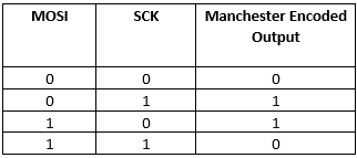
Observe the output on logic analyzer, it should follow the truth table as shown in the following diagram: