![]()
AC PWM generation
This example application shows how to use the Analog Comparator Peripheral library to generate a 1KHz PWM waveform.
Description
The AC peripheral is configured to generate analog PWM waveform by comparing the sine wave generated from the DAC with the reference voltage selected as a VDD scaler. The duty cycle of the analog PWM is changed by pressing a switch which changes the value of the VDD scaler.
Downloading and building the application
To clone or download this application from Github, go to the main page of this repository and then click Clone button to clone this repository or download as zip file. This content can also be downloaded using content manager by following these instructions.
Path of the application within the repository is apps/ac/ac_wav_gen/firmware .
To build the application, refer to the following table and open the project using its IDE.
| Project Name | Description |
|---|---|
| sam_ha1_xpro.X | MPLABX project for SAM HA1G16A Xplained Pro Evaluation Kit |
Setting up the hardware
The following table shows the target hardware for the application projects.
| Project Name | Board |
|---|---|
| sam_ha1_xpro.X | SAM HA1G16A Xplained Pro Evaluation Kit |
Setting up SAM HA1G16A Xplained Pro Evaluation Kit
- Connect a jumper between pin PA04 (Pin 16 of the EXT1 ) and PA02 (Pin 3 of the EXT1 header)
- Use the Logic Analyzer/Oscilloscope and probe PA18 pin (Pin 7 of the EXT1 header) to observe the PWM output
- Connect the Debug USB port on the board to the computer using a micro USB cable
Note:
ATSAMHA1G16A device in SAM HA1G16A Xplained Pro board is not recommended for new design, hence replace the device with ATSAMHA1G16AB device. Connect the supported external debugger to Cortex Debug Port
Running the Application
- Open the Terminal application (Ex.:Tera term) on the computer
- Connect to the EDBG Virtual COM port and configure the serial settings as follows:
- Baud : 115200
- Data : 8 Bits
- Parity : None
- Stop : 1 Bit
- Flow Control : None
- Build and Program the application using its IDE
-
Observe output message in console as follows (NOTE: Pin numbers will vary as per the device):
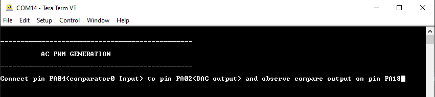
-
Observe the PWM waveform using the oscilloscope connected to the PWM output pin
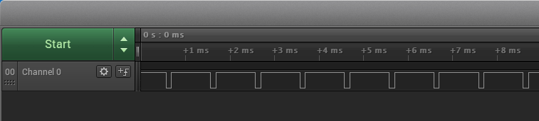
- Press switch to change the duty cycle of PWM waveform
Refer to the following table for pwm output and switch details:
| Board | PWM output pin | Switch |
|---|---|---|
| SAM HA1G16A Xplained Pro Evaluation Kit | PA18 pin (Pin 7 of the EXT1 header) | SW0 |