![]()
MCAN interrupt
This example shows how to use the MCAN module to transmit and receive CAN messages in interrupt mode.
Description
This application transmits and receives CAN messages on the CAN bus. To run this application, two evaluation boards of same type are required. These boards acts as different nodes on the CAN bus. Same application is programmed onto both the boards. Boards are connected to PC via UART. While running the application, user can send and receive CAN messages between the boards using UART console applications running on the PC.
MCAN Message RAM configuration
- Allocate MCAN Message RAM configuration in contiguous non-cacheable buffer in the application. For example, uint8_t CACHE_ALIGN mcan0MessageRAM[MCAN0_MESSAGE_RAM_CONFIG_SIZE] attribute((section(“.region_sram”)));
Downloading and building the application
To clone or download this application from Github, go to the main page of this repository and then click Clone button to clone this repository or download as zip file. This content can also be downloaded using content manager by following these instructions.
Path of the application within the repository is apps/mcan/mcan_normal_operation_interrupt/firmware .
To build the application, refer to the following table and open the project using its IDE.
| Project Name | Description |
|---|---|
| sam_9x75_eb.X | MPLABX project for SAM9X75-EB Evaluation Board |
Setting up AT91Bootstrap loader
To load the application binary onto the target device, we need to use at91bootstrap loader. Refer to the at91bootstrap loader documentation for details on how to configure, build and run bootstrap loader project and use it to bootstrap the application binaries.
Setting up the hardware
The following table shows the target hardware for the application projects.
| Project Name | Board |
|---|---|
| sam_9x75_eb.X | SAM9X75-EB Evaluation Board |
Setting up SAM9X75-EB Evaluation Board
Hardware required
| Name | Quantity |
|---|---|
| SAM9X75-EB Evaluation Board | 2 |
Setting up the board
- Connect SAM9X75-EB Evaluation Board to another SAM9X75-EB Evaluation Board as per the pin connections shown below
| SAM9X75-EB - 1 | SAM9X75-EB - 2 |
|---|---|
| CAN1_H | CAN1_H |
| CAN1_L | CAN1_L |
| GND | GND |
- Connect the DBGU0 J34 on board to the computer using a UART-FTDI cable (to enable debug com port)
- Connect the USB port J28 on board to the computer using a micro USB cable (to power the board)
Running the Application
- Build the application using its IDE
- Open the Terminal application (Ex.:Tera term) on the computer.
- Connect to the (USB to Serial) COM port and configure the serial settings as follows:
- Baud : 115200
- Data : 8 Bits
- Parity : None
- Stop : 1 Bit
- Flow Control : None
- Build and Program the application on both the boards using their respective IDEs
- In the console associated with board 1, press “1” to transmit a CAN message
- Transmitted message status will be displayed in the console window of board 1
- Received message will be displayed in the console window of board 2
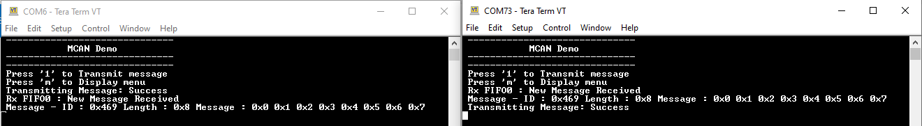
- Follow the sequence below to send and receive CAN message:
- Press ‘1’ on board 2
- If the steps are executed in this sequence, the final output in the consoles will be as below: