![]()
ADC automatic window comparison
This example application shows how to sample an analog input in polled mode and send the converted data to console using automatic window comparison of converted values.
Description
This example application shows how to use the ADC Peripheral library to perform automatic window comparison of converted values.
The ADC peripheral is configured to operate in window mode. In this example, Analog input voltage in the range of 0 V to 3.3 V is fed to the ADC input channel AD6. The ADC conversion is triggered by software and converted result is displayed on the console whenever input voltage goes below window lower threshold.
Downloading and building the application
To clone or download this application from Github, go to the main page of this repository and then click Clone button to clone this repository or download as zip file. This content can also be downloaded using content manager by following these instructions.
Path of the application within the repository is apps/adc/adc_automatic_window_comparison/firmware .
To build the application, refer to the following table and open the project using its IDE.
| Project Name | Description |
|---|---|
| sam_9x75_eb.X | MPLABX project for SAM9X75-EB Evaluation Board |
Setting up AT91Bootstrap loader
To load the application binary onto the target device, we need to use at91bootstrap loader. Refer to the at91bootstrap loader documentation for details on how to configure, build and run bootstrap loader project and use it to bootstrap the application binaries.
Setting up the hardware
The following table shows the target hardware for the application projects.
| Project Name | Board |
|---|---|
| sam_9x75_eb.X | SAM9X75-EB Evaluation Board |
Setting up SAM9X75-EB Evaluation Board
Setting up the board
- Connect the DBGU0 J34 on board to the computer using a UART-FTDI cable (to enable debug com port)
- Connect the USB port J28 on board to the computer using a micro USB cable (to power the board)
- Use a jumper wire to connect Pin AN of mikroBUS (AD6 is mapped to Port Pin PA30) to 3.3 V or GND (OR Use Potentiometer to vary input voltage from GND to 3.3 V and vice-versa)
Running the Application
- Build the application using its IDE
- Open the Terminal application (Ex.:Tera term) on the computer.
- Connect to the (USB to Serial) COM port and configure the serial settings as follows:
- Baud : 115200
- Data : 8 Bits
- Parity : None
- Stop : 1 Bit
- Flow Control : None
-
Console displays ADC Count and ADC Input Voltage whenever input voltage goes below lower window threshold value (output is not updated on console, if the values are within the threshold)
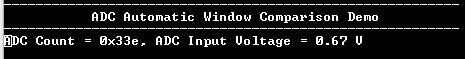
NOTE: Image provided in above step is for illustration purpose only. ADC count and ADC Input voltage are printed on the console whenever input voltage goes below 2.417 V ((3000/4095) * 3.3V)