![]()
WDT timeout
This example application shows how the watchdog timer resets by not feeding the watchdog on switch press.
Description
This example application shows how the WDT peripheral library resets the watchdog timer by not feeding the watchdog on switch press. The application sets up the watchdog to reset the device. The application also sets up the timer to blink an LED to emulate a process. A user switch press forces the device to wait in an infinite loop to emulate a deadlock. As a result a device reset is triggered as the watchdog counter overflows the bounded value.
Downloading and building the application
To clone or download this application from Github, go to the main page of this repository and then click Clone button to clone this repository or download as zip file. This content can also be downloaded using content manager by following these instructions.
Path of the application within the repository is apps/wdt/wdt_timeout/firmware .
To build the application, refer to the following table and open the project using its IDE.
| Project Name | Description |
|---|---|
| pic32mk_gp_db.X | MPLABX project for PIC32MK GP Development Kit |
| pic32mk_mcj_curiosity_pro.X | MPLABX project for PIC32MK MCJ Curiosity Pro Board |
| pic32mk_mcm_curiosity_pro.X | MPLABX project for PIC32MK MCM Curiosity Pro Board |
| pic32mk_mca_curiosity_pro.X | MPLABX project for PIC32MK MCA Curiosity Pro Board |
Setting up the hardware
The following table shows the target hardware for the application projects.
| Project Name | Board |
|---|---|
| pic32mk_gp_db.X | PIC32MK GP Development Kit |
| pic32mk_mcj_curiosity_pro.X | PIC32MK MCJ Curiosity Pro Board |
| pic32mk_mcm_curiosity_pro.X | PIC32MK MCM Curiosity Pro Board |
| pic32mk_mca_curiosity_pro.X | PIC32MK MCA Curiosity Pro Board |
Setting up PIC32MK GP Development Kit
- Connect the Debug USB port (J12) on the board to the computer using a micro USB cable
- Connect the USB to UART port (J25) on the board to the computer using a micro USB cable
Setting up PIC32MK MCJ Curiosity Pro Board
- Connect the Debug USB port (J1) on the board to the computer using a micro USB cable
Setting up PIC32MK MCM Curiosity Pro Board
- Connect the Debug USB port (J500) on the board to the computer using a micro USB cable
- Connect the USB to UART port (J400) on the board to the computer using a micro USB cable
Setting up PIC32MK MCA Curiosity Pro Board
- Connect the Debug USB port (J1) on the board to the computer using a micro USB cable
Running the Application
- Open the Terminal application (Ex.:Tera term) on the computer
- Connect to the EDBG Virtual COM port and configure the serial settings as follows:
- Baud : 115200
- Data : 8 Bits
- Parity : None
- Stop : 1 Bit
- Flow Control : None
- Build and Program the application project using its IDE
-
LED should be blinking and the console displays the following message
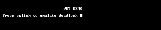
- Press the switch to put the system in a deadlock
-
LED should stop blinking and the console should print the following message
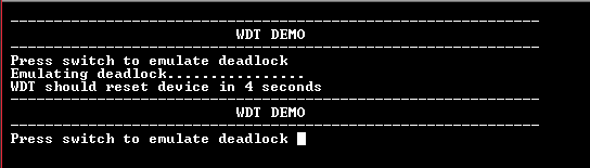
- WDT will reset the device in four seconds and the demonstration should restart
Refer the table below for details of switch and LED:
| Board | Switch Name | LED Name |
|---|---|---|
| PIC32MK GP Development Kit | S1 | LED1 |
| PIC32MK MCJ Curiosity Pro Board | SW200 | LED2 |
| PIC32MK MCM Curiosity Pro Board | SW1 | LED1 |
| PIC32MK MCA Curiosity Pro Board | SW200 | LED1 |