Do the following to run the demonstration:
Program the Device and Obtain Tools
- Compile, download, and run the program on the target device. While compiling, select the appropriate MPLAB X IDE project. Refer to Building the Application for details.
- Download the BM64 Software and Tools from here:
 http://www.microchip.com/wwwproducts/en/BM64, under Documentation > Software > (IS2064 / BM64 Software and Tools).

Unzip wherever it is convenient for you (e.g., C:\ IS2064_BM64 Software & Tools), and unzip any zip files contained within the folders.
Program the BM64 Module
The sequence of steps to program the BM64 Module are as follows:
- Run the tool C:\IS2064_BM64 Software & Tools\ DSPTool_IS206x_012_DualModeSPK1.1_v1.06.exe.
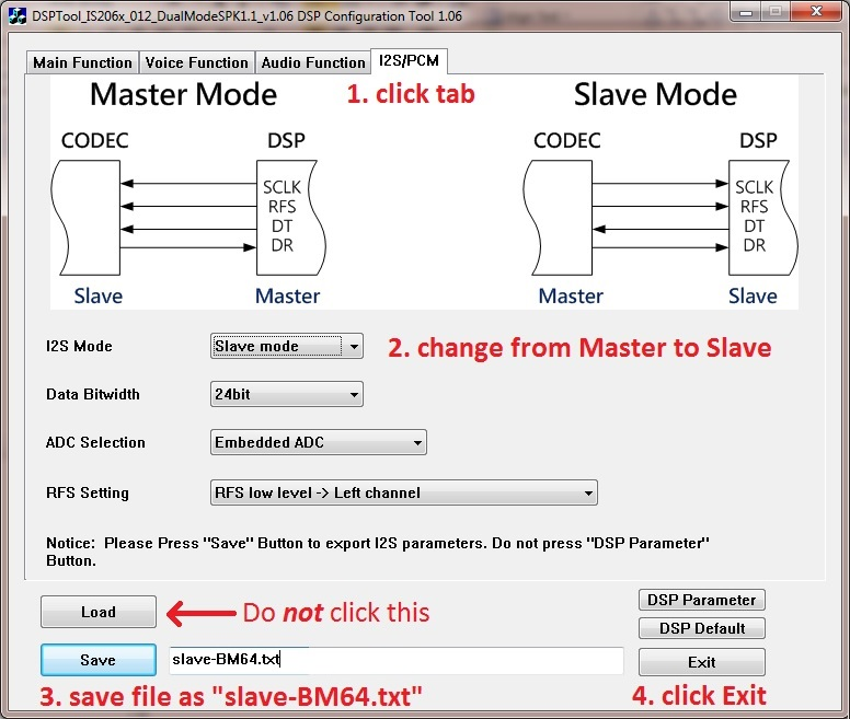
- Do not click on the Load button. Under the I2S/PCM tab, set the I2S Mode to “Slave mode”. Then, save the file as: slave-BM64.txt, and exit the DSP Tool.
- Run the tool: C:\IS2064_BM64 Software & Tools\UI Tool\UITool_IS206x_012_DualModeSPK1.1_v1.03.exe.
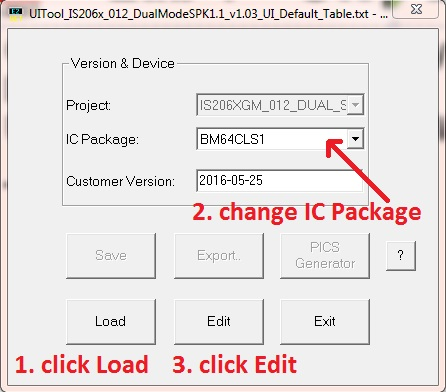
- Click Load, and load the file: UITool_IS206x_012_DualModeSPK1.1_v1.03_UI_Default_Table.txt. Then, change the IC Package type to BM64CLS1, and then click Edit.
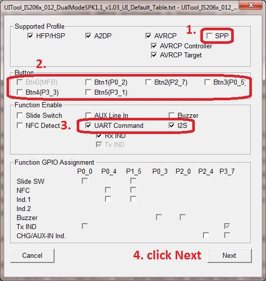
- Do the following In the Main dialog:
- Clear SPP
- Clear all of the Button check boxes
- Select UART Command and I2S, and then click Next
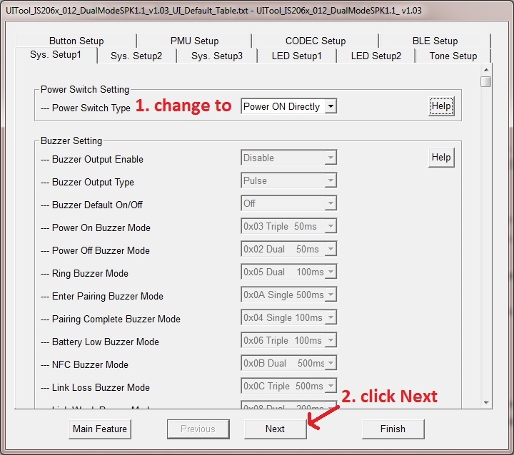
- Under the Sys Setup1 tab, change the Power Switch Setting/Power Switch Type to “Power ON Directly”, and then click Next.
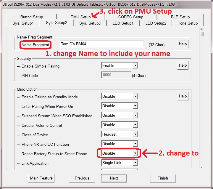
- Under the Sys Setup2 tab, change the Name Fragment to whatever you want (this name will show up in your Smart Phone’s Bluetooth setup). Change the Report Battery Status to Smart Phone setting to Disable, and then select the PMU Setup tab.
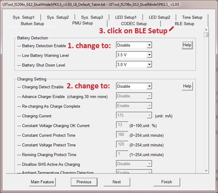
- Under PMU Setup, change Battery Detection/Battery Detection Enable to Disable and also change Charging Setting/ Charging Detect Enable to Disable, and then select the BLE Setup tab.
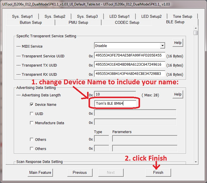
- Under BLE Setup tab, change the Device Name to whatever you want (this name will show up in your Smart Phone’s BLE setup), and then click Finish.
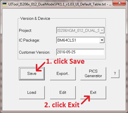
- Save the file as: BM64 UI, and then click Exit.
- Run the tool: C:\IS2064_BM64 Software & Tools\MPET Tool\MPET.exe.
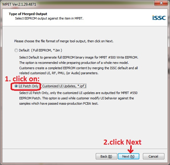
- Select UI Patch Only, and then click Next.
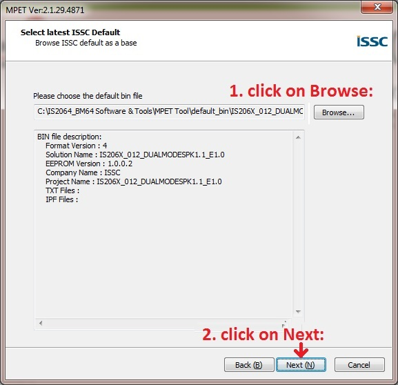
- Click Browse, and browse to the folder C:\IS2064_BM64 Software & Tools\MPET Tool\default_bin and select the .bin file there, and then click Next.
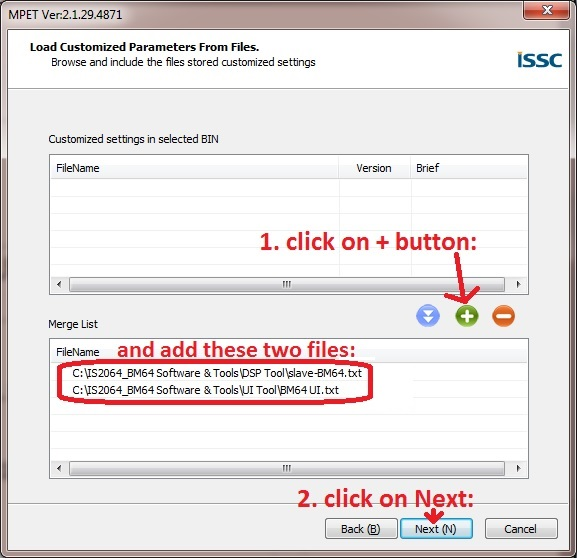
- Click the
 icon and load the file slave-BM64.txt that you saved earlier in Step 2. Click the
  icon again and load the file BM64 UI.txt you saved earlier in Step 10, and then click Next.
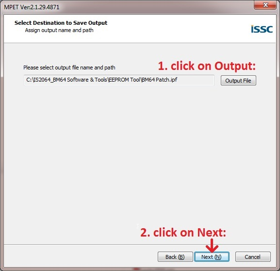
- Click the Output File button and save the file as BM64 Patch, and then click Next.
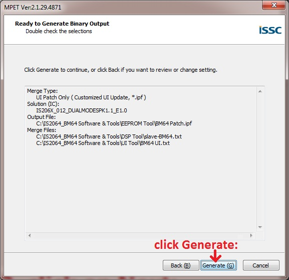
- On this screen, click Generate.
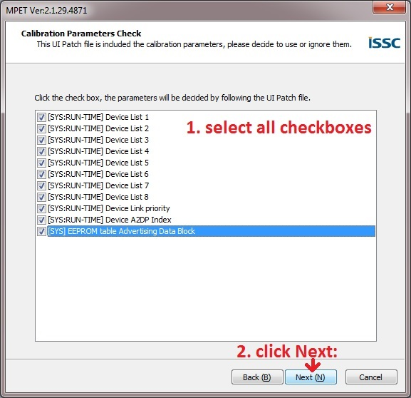
- In the next dialog, select all 11 check boxes, and then click Next.
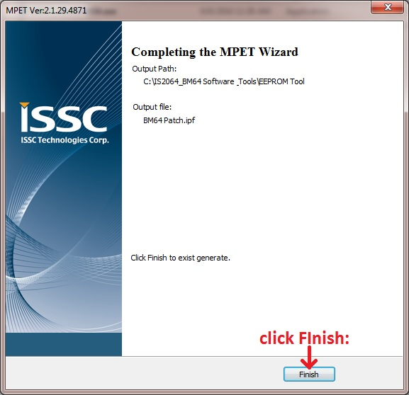
- Finally, click Finish.
Running the Demonstration on the Development Hardware
- Leave the USB cable plugged into the EDBG connector. Plug one end of a second USB cable into the micro-B USB jack labeled TARGET USB on the development board and the other into your PC. Set both switches SW1-1 and SW1-2 on the BM64 Module daughter board to the ON position.
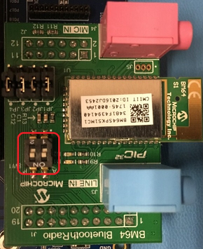
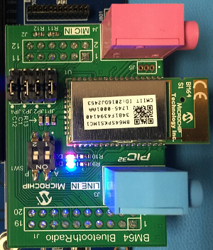
- Press and release SW1 (or SW0) on the development board. The two LEDs on the BM64 module should light up steady as shown in the following figure.
- Run the tool: C:\IS2064_BM64 Software & Tools\EEPROM Tool\ EEPROM_Tool_V4851.exe.
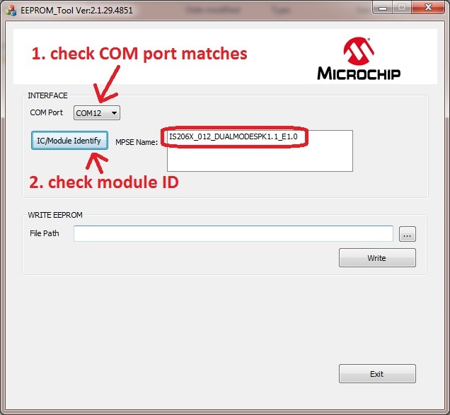
- Ensure that the correct COM Port is selected (you can use Window’s Device Manager to verify this), and then click IC/Module Identify. It should display one or two strings starting with IS206X…
- To the right of WRITE EEPROM, click on the
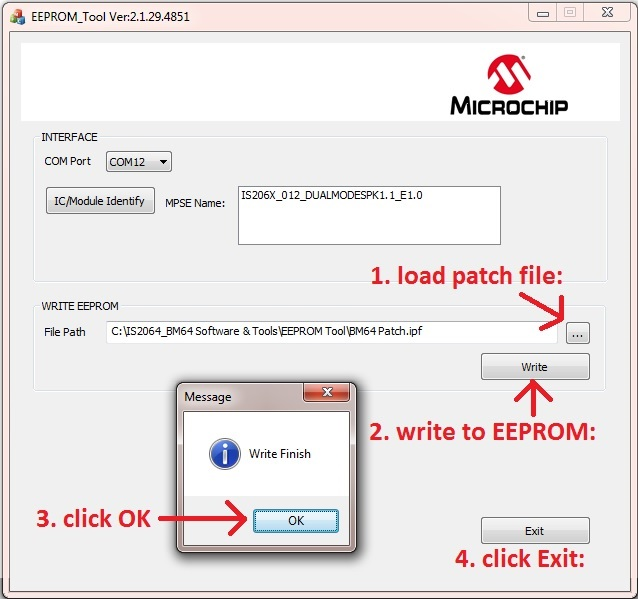
 button and browse to the BM64 Patch.ipf file you specified earlier, and then click Write. When done and the dialog appears, click OK, and then click Exit.
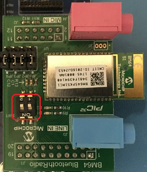
- On the BM64 Module Daughter Board, set both switches SW1-1 and SW1-2 to the OFF position.
- On the development board, press and release the SW1 (or SW0) button. The two LEDs on the BM64 Module should turn off. The BM64 Module is now ready to run with the BM64_a2dp_hfp application.
Control Descriptions
|
Control |
|
|
SW1 (SW0 on some boards) |
Resets then enables the BM64 Bluetooth module |
Bluetooth Demonstrations > BM64 and BM71 Driver Demonstrations > BM64_bootloader > Running the Demonstration
|
MPLAB Harmony Bluetooth Help
|