In this demonstration application, the PIC32 or SAM processor on the development board is used as a bootloader to configure the EEPROM of the BM64 module on the BM64 Module Daughter Board. This can be done prior to using the BM64 module with the ble_comm application, for example to configure a unique BLE name for the module, or to configure the BM64 module as an I2S Slave to work the a2dp_hfp application.
When the application is running, the PIC32 or SAM processor appears as a virtual COM port on the PC.
There are two different projects packaged in this application.
PIC32 MZ EF Curiosity 2.0 Project:
One project runs on the PIC32 MZ EF Curiosity 2.0 board, using the PIC32MZ2048EFM144 microcontroller with 2 MB of Flash memory and 512 KB of RAM running at 198 MHz. The PIC32 MZ EF Curiosity 2.0 board includes the following features:
- Four push buttons (SW1-SW4, only SW1 is used)
- Four LEDs (LED1-LED4, only LED1 is used)
- USB Device interface
- Two X32 sockets, one of which is used for the BM64 Bluetooth module.
|
|
The PIC32 MZ EF Curiosity 2.0 board does not include the BM64 Bluetooth Module Daughter Board. It must be purchased separately from microchipDIRECT, part number AC320032-3. |
The program takes up to approximately 2% (43 KB) of the PIC32MZ2048EFM144 microcontroller’s program space, and 1% (2.8 KB) of the RAM. No heap is used.
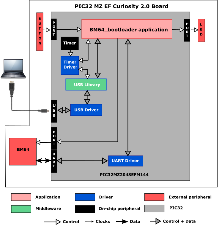
The following figure illustrates the application architecture:
SAM E70 Xplained Ultra Project:
One project runs on the SAM E70 Xplained Ultra board, which contains a ATSAME70Q21B microcontroller with 2 MB of Flash memory and 384 KB of RAM running at 300 MHz with the following features:
- One push button (SW1, may be labeled as SW0 on some boards)
- Two user LEDs (LED1 and 2, first LED may be labeled as LED0 on some boards))
- USB Device interface
- One X32 socket, used for the BM64 Bluetooth module.
|
|
The SAM E70 Xplained Ultra board does not include the BM64 Bluetooth Module Daughter Board. It must be purchased separately from microchipDIRECT, part number AC320032-3. |
The program takes up only about 1% (16 KB) of the ATSAME70Q21B microcontroller’s program space, and 1% (2.5 KB) of its RAM.
The following figure illustrates the application architecture:
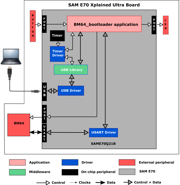
The same application code is used without change for both projects.
The PIC32 or SAM microcontroller (MCU) runs the application code, and communicates with the BM64 over a UART/USART interface operating at 115,200 baud. The BM64 module contains its own Bluetooth stack, but it is not used in this application since it is only used to update the BM64’s configuration. UART/USART references in the source code are generic, e.g. UARTn_Read These are resolved into actual calls in user.h using #defines depending on whether the MCU uses either a UART or USART, and which one, e.g.
#define UARTn_Read UART1_Read
As with any MPLAB Harmony application, the SYS_Initialize function, which is located in the system_init.c source file, makes calls to initialize various sub-systems, such as the clock, ports, board support package (BSP), USB, BM64, timers, UART/USART, and interrupts.
The USB driver and the application state machines are updated through calls located in the SYS_Tasks function in the system_tasks.c file.
The program is derived from the cdc_serial_emulator demonstration program. The USB interface looks like a virtual communications port on the PC. It reads characters from the host PC over the USB interface and sends them straight through to the BM64 over the UART/USART; likewise, it reads characters from the BM64 via the UART/USART and sends them back to the host PC.
The application code is contained in the source file app.c, which contains a state machine (APP_Tasks) for the application, as well as two state machines for handling the USB interface. It first initializes the application, then receives a handle to the USB Device driver by calling USB_DEVICE_Open function with a mode of DRV_IO_INTENT_READWRITE. Then it sets up a fixed baud rate of 115,200 baud, and registers an event handler, APP_USBDeviceEventHandler as a callback with the USB driver. It then does initial calls to both UARTn_Read and USB_DEVICE_CDC_Read to start things off.
The program then looks to see if any characters have come in through from the USB interface from the PC, and if so writes them to the transmit side of the UART/USART interface to the BM64 using a UARTn_Write call. After each write, it stays in the same state to see if there are any more characters coming it. Once all of the pending characters have been written, it issues a new USB_DEVICE_CDC_Read call and then looks for characters from the BM64.
As characters come in from the UART/USART, it sends them on to the PC using a USB_DEVICE_CDC_Write call. After each write, it stays in the same state to see if there are any more characters coming it. Otherwise it issues a new call to UARTn_Read, and goes back to check for characters coming from the USB interface.
The APP_Tasks function also takes care of polling the buttons, and if SW1 is pressed, asserts the BM64’s reset line (STBYRST) line low for 200 ms, followed by a 50 ms delay, and then asserts the BM64’s MFB (multi-function button line) high for 200 ms.
- Sending and receiving characters between the USB device interface of the PIC32 or SAM MCU and a host PC using the CDC Function Driver (see USB Device Driver Library)
- Sending and receiving characters between the UART/USART of the PIC32 or SAM MCU and the BM64. (see UART/USART Driver Library)
- Processing of button pushes on the development board using a state machine for contact debouncing (see Ports Peripheral Library)
- Use of two timers: one as a periodic 1 ms timer for the application for debouncing the pushbutton, and a second used by the BM64 driver (see Timer Driver Library)
For projects using the PIC32MZ:
When building a new application, start by creating a 32-bit MPLAB Harmony 3 project in MPLAB X IDE by selecting File > New Project. Chose the Configuration name the based on the BSP. Select the appropriate processor (PIC32MZ2048EFM144).
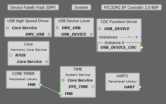
In the Available Components section of MHC, under Board Support Packages, select PIC32MZ EF Curiosity 2.0 BSP. Also in the Available Components section, under Libraries->USB->Device Stack, choose CDC Function Driver. Answer Yes to all questions except activating FreeRTOS. Finally choose Peripherals->UART1 and Peripherals->CORE TIMER, and under Harmony->System Services, choose TIME. Connect CORE TIMER to the TIME block.
The Project Graph should look something like this:
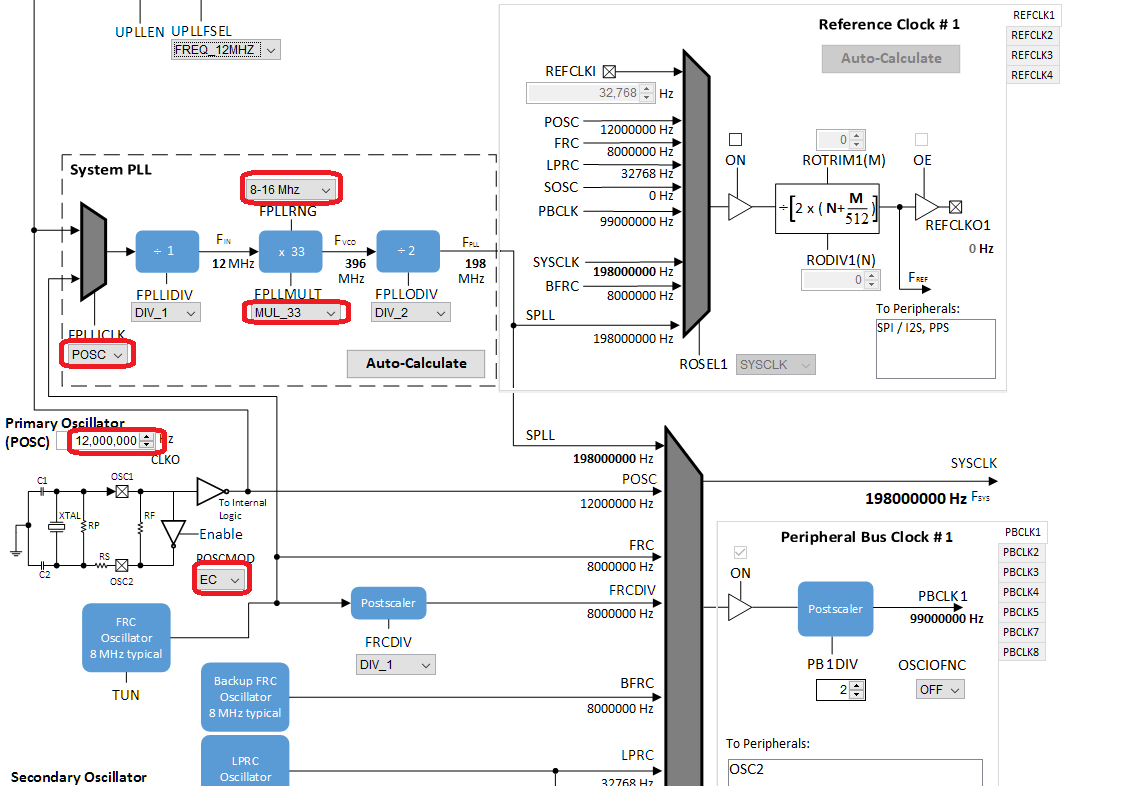
Click on Tools->Clock Diagram and change the settings as shown:
Under Tools->Pin Manager, make the following assignments:
|
Pin |
Pin ID |
Name |
Funcion |
Direction |
Latch |
|
6 |
RC1 |
U1RX |
U1RX |
|
|
|
9 |
RB2 |
STBYRST |
GPIO |
Out |
Low |
|
13 |
RC4 |
U1TX |
U1TX |
|
|
|
58 |
RF12 |
BM64_MFB |
GPIO_AH |
Out |
High |
For projects using the SAME70:
When building a new application, start by creating a 32-bit MPLAB Harmony 3 project in MPLAB X IDE by selecting File > New Project. Chose the Configuration name the based on the BSP. Select the appropriate processor (ATSAME70Q21B).
In the Available Components section of MHC, under Board Support Packages, select SAM E70 Xplained Ultra BSP. Also in the Available Components section, under Libraries->USB->Device Stack, choose CDC Function Driver. Answer Yes to all questions except activating FreeRTOS. Finally choose Peripherals->USART0 and Peripherals->TC0, and under Harmony->System Services, choose TIME. Connect TC0 to the TIME block.
The Project Graph should look something like this:
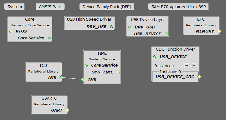
In the Project Graph, click on the USB Device Layer, and in the Configuration Options dialog change Product ID Selection to cdc_serial_emulator_demo.
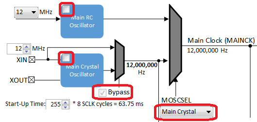
Click on USART0 in the graph, and change the Baud Rate to 115,200 in the Configuration Options dialog. In the Clock Diagram, set MOSCEL to Main Crystal, check the Bypass checkbox, and uncheck the RC Crystal Oscillator and Main Crystal Oscillator boxes:
Under Tools->Pin Manager, make the following assignments:
|
Pin |
Pin ID |
Name |
Funcion |
Direction |
Latch |
|
20 |
PB1 |
USART0_TXD0 |
USART0_TXD0 |
|
|
|
21 |
PB0 |
USART0_RXD0 |
USART0_RXD0 |
|
|
|
26 |
PB2 |
BM64_MFB |
GPIO |
Out |
Low |
|
98 |
PD11 |
STBYRST |
GPIO |
Out |
High |
|
141 |
PB8 |
USB_VBUS_SENSE |
GPIO |
In |
|
|
Name |
Description |
|
This section identifies the MPLAB X IDE project name and location and lists and describes the available configurations for the demonstration. | |
|
This section describes how to configure the supported hardware. | |
|
This section describes how to run the demonstration. |
|
MPLAB Harmony Bluetooth Help
|