In this demonstration application, the Bluetooth® Low Energy (BLE) capabilities of the BM64 Module Daughter Board, or the BLE-only BM71 XPRO Board are used to send a string of characters to a smartphone when one of the push buttons is pressed on the board, and to receive a string of characters from the smartphone causing an LED to turn on or off on the board.
Both the BM64 and BM71 provide what is called Transparent Service, which allows generic text strings to be sent back and forth between a server (e.g., BM64/BM71) and a client (e.g., smartphone). Therefore, users can add their own structure on top of this capability and implement their own protocol such as a command/data format. The Transparent Service provides a BLE substitute for the Serial Port Protocol (SPP) of classic Bluetooth for use with an Apple® iPhone®, which does not support SPP.
The BM71 also supports standard GATT predefined profiles, however the current BM71 driver does not provide access to these. The current BM64 module does not support standard BLE GATT predefined profiles.
To successfully run this application with the BM64, you will need an iPhone 4s or later which supports Bluetooth 4.0 or later. For the BM71, you can use either an iPhone or Android phone that supports Bluetooth 4.0 or later.
|
|
Note: |
This MPLAB Harmony application has been designed to also work with a smartphones running Android™, as well as an iPhone; however, the firmware on the BM64 module currently does not support connections to Android smartphones. If you need this application to work with an Android™ phone, please contact your local Microchip Marketing Representative as to the possibility of getting an update to the BM64 firmware. |
To know more about the MPLAB Harmony Bluetooth Drivers, configuring the Bluetooth Drivers, and the APIs provided by the Bluetooth Drivers, refer to Codec Driver Libraries.
There are ten different projects packaged in this application.
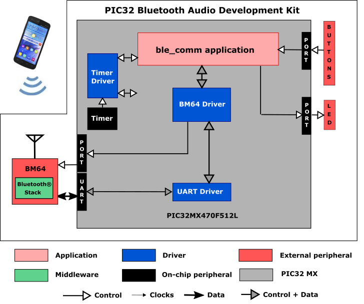
PIC32_MX Bluetooth Audio Development Kit Project:
One project runs on the Bluetooth Audio Development Kit (BTADK). It uses the microcontroller installed on the board, namely the PIC32MX470F512L with 512 KB of Flash memory and 128 KB of RAM running at 96 MHz. The BTADK includes the following features:
- Six user push buttons (SW1-SW6, only SW1 is used)
- Five user LEDs (D5-D9, only D5 is used)
- USB Device interface
- Two X32 sockets, one of which is used for the BM64 Bluetooth module.
The BTADK also includes an LCD display and USB Host interface, neither of which are used in this project.
|
|
The SAM E70 Xplained Ultra does not include the BM64 Bluetooth Module Daughter Board. It must be purchased separately from microchipDIRECT, part number AC320032-3. |
The program takes up to approximately 7% (34 KB) of the microcontroller’s program space, and 3% (3.5 KB) of the RAM. No heap is used.
The following figure illustrates the application architecture:
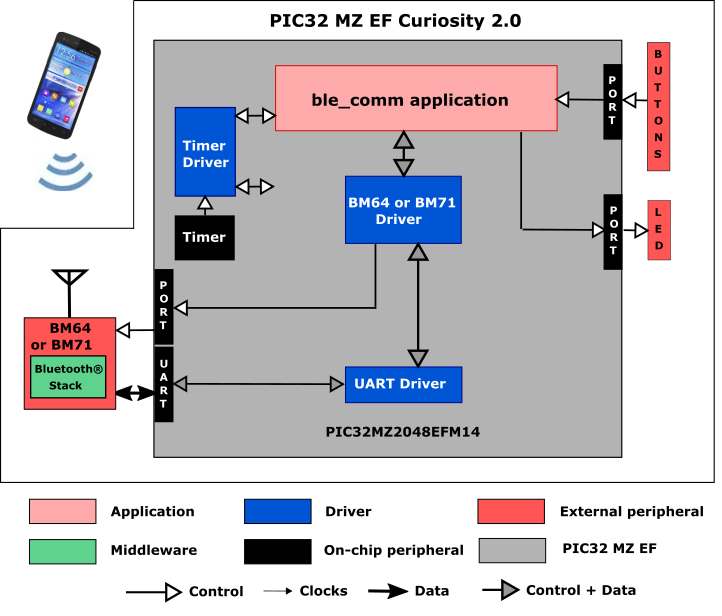
PIC32 MZ EF Curiosity 2.0 Project:
Two projects run on the PIC32 MZ EF Curiosity 2.0 board, using the PIC32MZ2048EFM144 microcontroller with 2 MB of Flash memory and 512 KB of RAM running at 198 MHz. The PIC32 MZ EF Curiosity 2.0 board includes the following features:
- Four user push buttons (SW1-SW4, only SW1 is used)
- Four user LEDs (LED1-LED4, only LED1 is used)
- USB Device interface
- Two X32 sockets, one of which is used for the BM64 Bluetooth module.
|
|
The PIC32 MZ EF Curiosity 2.0 board does not include the BM64 Bluetooth Module Daughter Board. It must be purchased separately from microchipDIRECT, part number AC320032-3. |
The program takes up to approximately 1% (16 KB) of the PIC32MZ2048EFM144 microcontroller’s program space, and 1% (2.5 KB) of the RAM. No heap is used.
The following figure illustrates the application architecture:
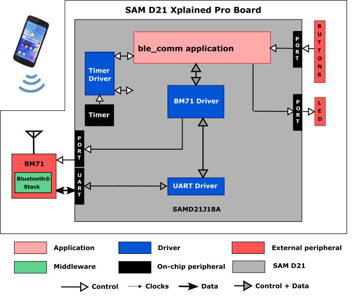
SAM D21 Xplained Pro Project:
One project runs on the SAM E54 Xplained Pro Board, which contains a SAMD21J18A microcontroller with 256 KB of Flash memory and 32 KB of RAM running at 48 MHz using the following features:
- One user push button (SW0)
- One user LED (LED0)
- Three XPRO connectors, one of which is used for the BM71 XPRO board.
|
|
The SAM D21 Xplained Pro board does not include the BM71 XPRO board. It must be purchased separately from microchipDIRECT, part number DM164146. |
The following figure illustrates the application architecture:
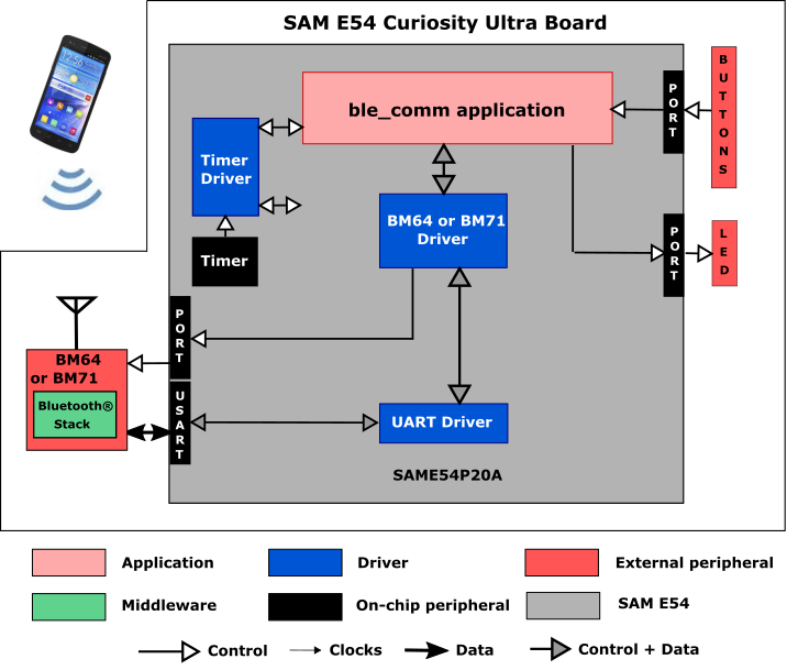
SAM E54 Curiosity Ultra Project:
Two projects run on the SAM E54 Curiosity Ultra Board, which contains a ATSAME54P20A microcontroller with 1 MB of Flash memory and 256 KB of RAM running at 48 MHz using the following features:
- Two push buttons (SW1 and SW2)
- Two user LEDs (LED1 and 2)
- One X32 socket, used for the BM64 Bluetooth module daughterboard.
The SAM E54 Curiosity Ultra does not include the BM64 Bluetooth Module Daughter Board. It must be purchased separately from microchipDIRECT, part number AC320032-3.
The ATSAME54P20A microcontroller (MCU) runs the application code, and communicates with the BM64 over a USART interface operating at 115,200 baud. The BM64 module contains its own Bluetooth stack, so it is unnecessary to include a software Bluetooth stack in the MCU. The program takes up about 2% (23 KB) of the ATSAME54P20A microcontroller’s program space, about 1% (3 KB) of its RAM. No heap is used.
The following figure illustrates the application architecture:
SAM E54 Xplained Pro Project:
One project runs on the SAM E54 Xplained Pro Board, which contains a ATSAME54P20A microcontroller with 1 MB of Flash memory and 256 KB of RAM running at 48 MHz using the following features:
- One user push button (SW0)
- One user LED (LED0)
- Three XPRO connectors, one of which is used for the BM71 XPRO board.
|
|
The SAM E54 Xplained Pro board does not include the BM71 XPRO board. It must be purchased separately from microchipDIRECT, part number DM164146. |
The following figure illustrates the application architecture:
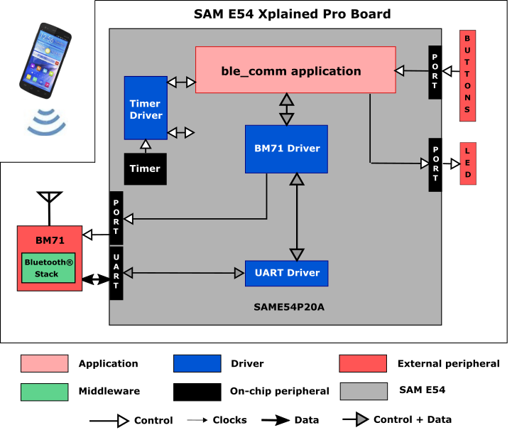
SAM E70 Xplained Ultra Projects (no display):
Two projects run on the SAM E70 Xplained Ultra Board without a display, , which contains a ATSAME70Q21B microcontroller with 2 MB of Flash memory and 384 KB of RAM running at 300 MHz with the following features:
- One user push button (SW1, may be labeled as SW0 on some boards)
- Two user LEDs (only one is used)
- One X32 socket, used for the BM64 Bluetooth module daughterboard.
|
|
The SAM E70 Xplained Ultra board does not include the BM64 Bluetooth Module Daughter Board. It must be purchased separately from microchipDIRECT, part number AC320032-3. |
The following figure illustrates the application architecture (RTOS not shown):
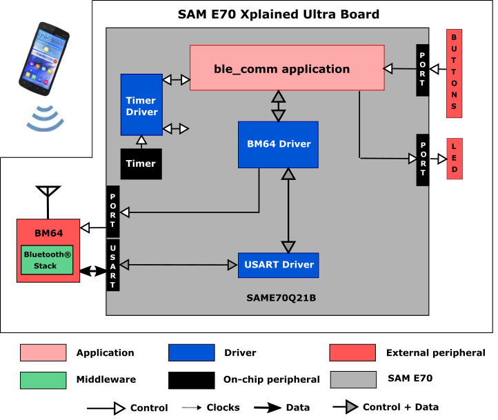
The ATSAME70Q21B microcontroller (MCU) runs the application code, and communicates with the BM64 over a USART interface operating at 115,200 baud. The BM64 module contains its own Bluetooth stack, so it is unnecessary to include a software Bluetooth stack in the MCU. The non-RTOS version of the program takes up about 1% (21 KB) of the ATSAME70Q21B microcontroller’s program space, about 1% (3 KB) of its RAM. No heap is used. For the FreeRTOS project, the program takes up to approximately 2% (43 KB) of the ATSAME70Q21B microcontroller’s program space, and 1% (26 KB) of the RAM. No heap is used.
SAM E70 Xplained Ultra Project with LCD display:
This project runs on the SAM E70 Xplained Ultra Board, which contains a ATSAME70Q21B microcontroller with 2 MB of Flash memory and 384 KB of RAM running at 300 MHz using the following features:
• WM8904 Codec Daughter Board mounted on a X32 socket
• PDA TM4301B 480x272 (WQVGA) Display
|
|
The SAM E70 Xplained Ultra board does not include either the WM8904 Audio Codec daughterboard or the TM4301B graphics card, which are sold separately on microchipDIRECT as part numbers AC328904 and AC320005-4, respectively. |
The following figure illustrates the application architecture, for this project:
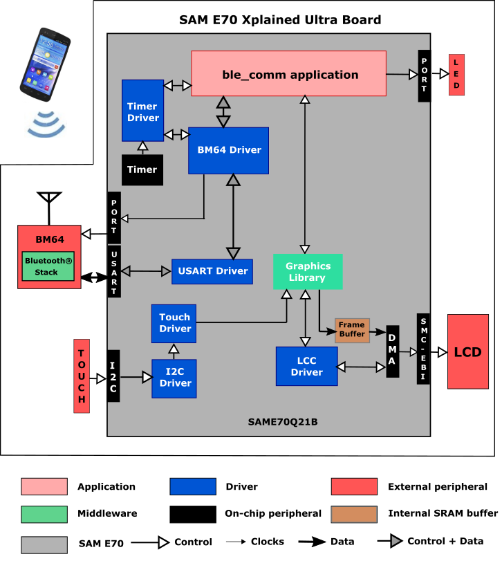
The program takes up to approximately 16% (318 KB) of the ATSAME70Q21B microcontroller’s program space, and 71% (338 KB) of the RAM, including a 32 KB heap.
Except for the user interface, the same application code is used without change between the various projects.
As with any MPLAB Harmony application, the SYS_Initialize function, which is located in the system_init.c source file, makes calls to initialize various subsystems, such as the clock, ports, board support package (BSP), PMP, BM64/BM71, timers, UART/USART, graphics, and interrupts.
The BM64 or BM71 driver, graphics, and the application state machines are all updated through calls located in the SYS_Tasks function in system_tasks.c file. Interrupt handlers in the system_interrupt.c file are only used for receiving characters from the UART/USART and for the two timers.
The application code is contained in two principal source files. The first, app.c, contains a simple state machine (APP_Tasks), which first initializes the application, and then while idle. In the non-GUI version of the program, it calls a secondary state machine, buttonTasks, to process any button pushes (resulting in a call to the BM64 or BM71 driver to send a string from the Bluetooth module to a connected smartphone). In the GUI version, an event handler for the touch screen processes the on-screen button press and sends a string from the BM64 to a connected smartphone.
APP_Tasks also calls another secondary state machine (bleTasks), which is located in the source file ble.c to process BLE-related tasks. bleTasks receives a handle to the BM64 or BM71 driver by calling DRV_BT_Open, and then registers an event handler, _BLEEventHandler, as a callback with the BM64/BM71 driver. The callback is called when either a message is received from the Bluetooth module or when the BLE status changes (i.e., when it is connected or disconnected). Both of these actions result in updates to the LED and/or display.
For all but one of the projects, the button and LEDs are interfaced using GPIO pins. In the remaining project, a 480x272 LCD screen is used as the user interface.
- Use of the BM64 or BM71 Bluetooth Driver Library
- At a lower level, the BM64/BM71 Driver uses the a UART or USART PLIB to communicate with the Bluetooth module
- BLE advertising
- Connection of BM64/BM71 to the smartphone
- Display of service and characteristic UUIDs on the smartphone
- Sending of a text string from the development board/Bluetooth module to the smartphone when a button is pressed
- Sending of a text string from the smartphone to the Bluetooth module/development board, causing an LED to turn on or off.
- Sending and receiving characters between the UART/USART of the MCU and the BM64/BM71.
- For all but one of the projects, processing of button pushes on the development board using a state machine for contact debouncing (see Ports Peripheral Library)
- For the project using a display, responding to touch events.
- Use of two timers: one as a periodic 1 ms timer for the application for button debouncing or touch button timing, and a second used by the BM64 or BM71 driver (see Timer Driver Library)
For the projects using the PIC32MX:
When building a new application, start by creating a 32-bit MPLAB Harmony 3 project in MPLAB X IDE by selecting File > New Project. Chose the Configuration name the based on the BSP. Select the appropriate processor (PIC32MX470F512L).
In MHC, under Available Components select the BSP PIC32MX Bluetooth Audio Development Kit. Under Bluetooth->Templates, double-click on BM64 Bluetooth. Answer Yes to all questions.
You should end up with a project graph that looks like this, after rearranging the boxes:
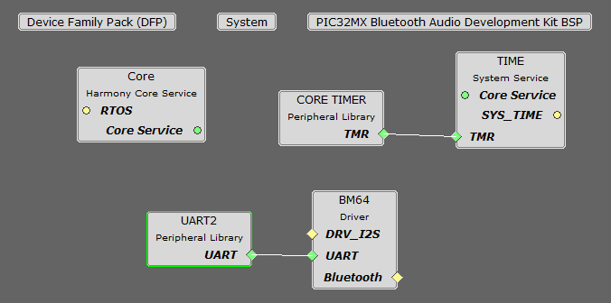
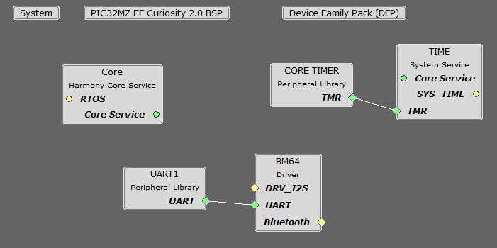
For projects using the PIC32MZ and BM64:
When building a new application, start by creating a 32-bit MPLAB Harmony 3 project in MPLAB X IDE by selecting File > New Project. Chose the Configuration name the based on the BSP. Select the appropriate processor (PIC32MZ2048EFM144).
In MHC, under Available Components select the BSP PIC32MZ EF Curiosity 2.0. Under Bluetooth->Templates, double-click on BM64 Bluetooth. Answer Yes to all questions.
You should end up with a project graph that looks like this, after rearranging the boxes:
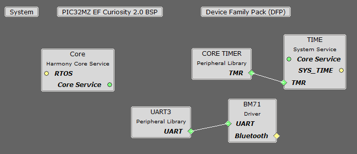
For projects using the PIC32MZ and BM71:
When building a new application, start by creating a 32-bit MPLAB Harmony 3 project in MPLAB X IDE by selecting File > New Project. Chose the Configuration name the based on the BSP. Select the appropriate processor (PIC32MZ2048EFM144).
In MHC, under Available Components select the BSP PIC32MZ EF Curiosity 2.0. Under Bluetooth->Templates, double-click on BM71 Bluetooth. Answer Yes to all questions.
You should end up with a project graph that looks like this, after rearranging the boxes:
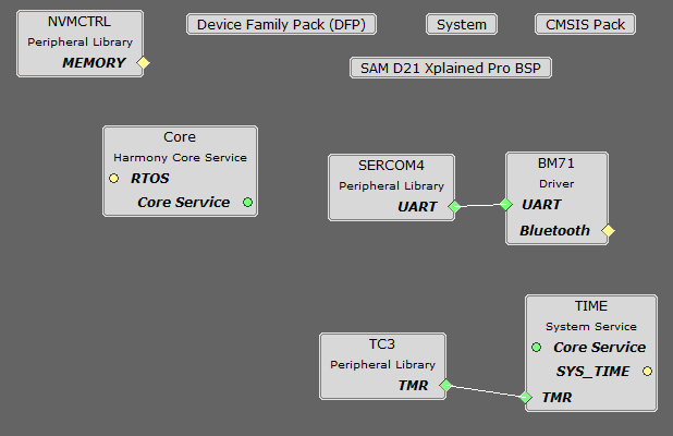
For projects using the SAMD21:
When building a new application, start by creating a 32-bit MPLAB Harmony 3 project in MPLAB X IDE by selecting File > New Project. Chose the Configuration name the based on the BSP. Select the appropriate processor (ATSAMD21J18A).
In MHC, under Available Components select the BSP SAM D21 Xplained Pro. Under Bluetooth->Templates, double-click on BM64 Bluetooth. Answer Yes to all questions.
You should end up with a project graph that looks like this, after rearranging the boxes:
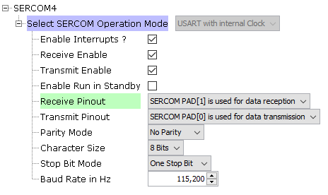
Click on SERCOM4 in the graph, and change the Receive Pinout to PAD[1] as shown below:
For projects using the SAME54 and BM64:
When building a new application, start by creating a 32-bit MPLAB Harmony 3 project in MPLAB X IDE by selecting File > New Project. Chose the Configuration name the based on the BSP. Select the appropriate processor (ATSAME54P20A).
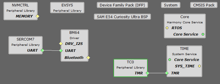
In MHC, under Available Components select the BSP SAM E54 Curiosity Ultra. Under Bluetooth->Templates, double-click on BM64 Bluetooth. Answer Yes to all questions.
You should end up with a project graph that looks like this, after rearranging the boxes:
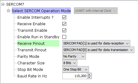
Click on SERCOM7 in the graph, and change Receive Pinout to "SERCOM Pad[1] is used for data reception" in the Configuration Options dialog.
For projects using the SAME54 and BM71:
When building a new application, start by creating a 32-bit MPLAB Harmony 3 project in MPLAB X IDE by selecting File > New Project. Chose the Configuration name the based on the BSP. Select the appropriate processor (ATSAME54P20A).
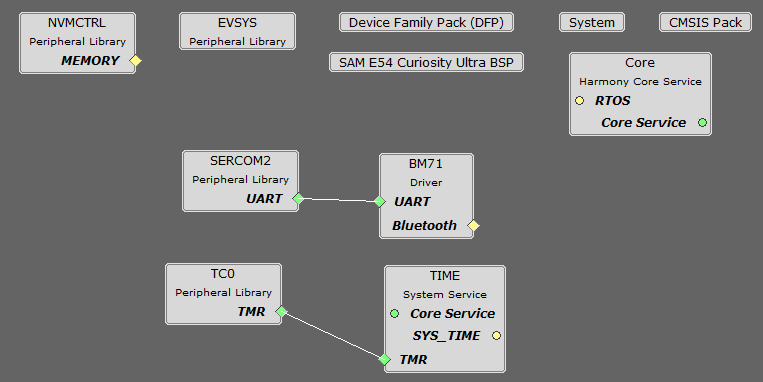
In MHC, under Available Components select the BSP SAM E54 Curiosity Ultra or BSP SAM E54 Xplained Pro. Under Bluetooth->Templates, double-click on BM71 Bluetooth. Answer Yes to all questions.
You should end up with a project graph that looks one of these, after rearranging the boxes:
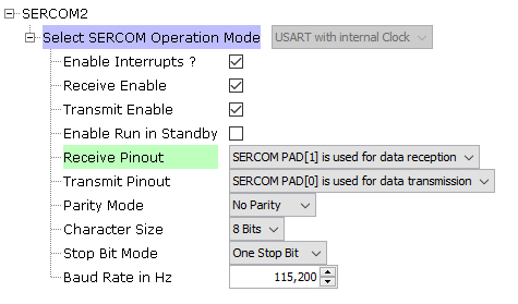
If using the SAM E54 Curiosity Ultra, click on SERCOM2 in the graph, and change the Receive Pinout to PAD[1] as shown below:
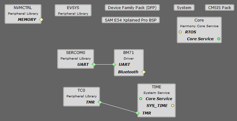
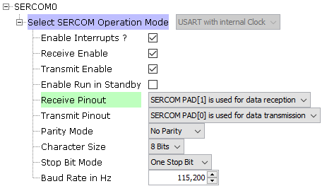
If using the SAM E54 Xplained Pro, click on SERCOM0 in the graph, and change the Receive Pinout to PAD[1] as shown below:
For projects using the SAME70:
When building a new application, start by creating a 32-bit MPLAB Harmony 3 project in MPLAB X IDE by selecting File > New Project. Chose the Configuration name the based on the BSP. Select the appropriate processor (ATSAME70Q21B).
In MHC, under Available Components select the BSP SAM E70 Xplained Ultra. Under Bluetooth->Templates, double-click on BM64 Bluetooth. Answer Yes to all questions.
You should end up with a project graph that looks like this, after rearranging the boxes:
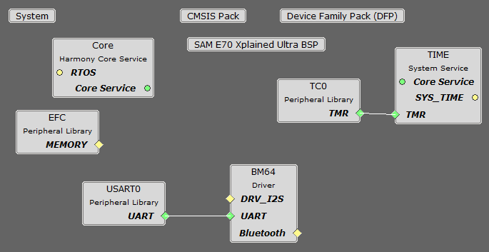
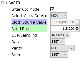
Click on USART0 in the graph, and change the Baud Rate to 115,200 in the Configuration Options dialog.
In Tools->Clock Diagram, in the Clock Diagram, set MOSCEL to Main Crystal, check the Bypass checkbox, and uncheck the RC Crystal Oscillator and Main Crystal Oscillator boxes, to make use of the 12 MHz external oscillator:
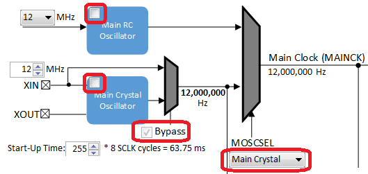
If building an application that is going to use the 480x272 display, then do the following instead. In the MHC, under Available
Components select the BSP (SAM E70 Xplained Ultra). Under Graphics>Templates, double-click on Aria Graphics w/ PDA
TM4301B Display. Answer Yes to all questions except for the one regarding FreeRTOS; answer No to that one.
Then under Audio>Templates, double-click on WM8904 Codec. Answer Yes to all questions.
You should end up with a project graph that looks like this, after rearranging the boxes:
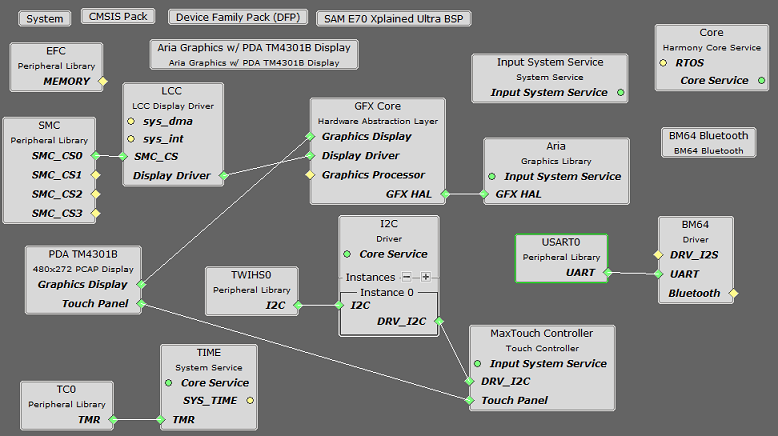
If using FreeRTOS, in the code you will need to move the call to DRV_WM8904_Tasks(sysObj.drvwm8904Codec0); from the
SYS_Tasks function in src/config/<config_name>/tasks.c to inside the while(1) loop of _APP_Tasks (just before the call to
APP_Tasks), or create a separate task for it.
|
Name |
Description |
|
This section identifies the MPLAB X IDE project name and location and lists and describes the available configurations for the demonstration. | |
|
This section describes how to configure the supported hardware. | |
|
This section describes how to run the demonstration. |
|
MPLAB Harmony Bluetooth Help
|