1.1.4 PIC32CX-BZ2 Standalone Bootloader Component Help
PIC32CX-BZ2 bootloader is a standalone harmony component, Using it, one can generate bootloader which is a program that is loaded on internal flash memory and gets executed every time the device powers up or resets.
Bootloader can be used to upgrade firmware on a target device without the need for an external programmer or debugger. It does not fully operate on the device, but can perform various functions prior to starting the main application
- Loads firmware images to flash over the serial connection using a tool or python script, known as Device Firmware Upgrade (DFU)
- Provides application protection for firmware
- Replaces application firmware
- Starts the application
- If the device wakes from deep sleep, then bootloader directly jumps to the application
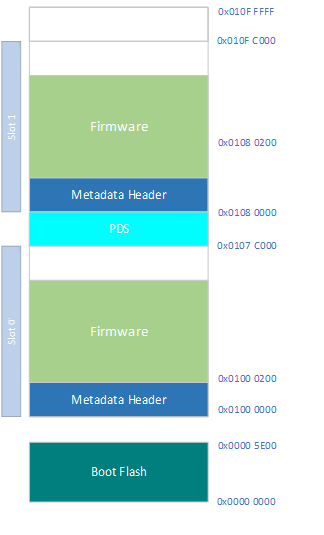
Memory Information and Layout of PIC32CXBZ2 device
| Memory Area | Purpose |
|---|---|
| Boot Flash Size is 0x0 to 0x5E00 – (~24KB) | The memory where bootloader code runs |
| Slot 0 base address - 0x01000000 | The memory where the application firmware runs and the memory where the bootloader copies the new application firmware |
| Slot 1 base address - 0x01080000 | The memory where the received image(Either through DFU or any other way) gets stored. and the memory where bootloader looks for the new image to copy into the Slot 0 |
The full memory layout can be found here
Boot Flash
In PIC32CXBZ2, 24KB boot flash memory is separated from the main execution memory. This boot flash is used for bootloader code
Metadata Header
Format of image meta-data header are described below. Notice that some of the elements in the header is reserved for future expansion and they are not used in this version of bootloader implementation
| Offset | Name | Description |
|---|---|---|
| Metadata Header | ||
| 0x00:0x07 | Filler | Set to all zero |
| 0x08:0x0D | MANU_IDENTIFIER * | “MCHP” ASCII String Identifier |
| 0x0C:0x0F | Filler | Set to all zero |
| 0x10:0x13 | SEQ_NUM * | Metadata Sequence Number of the image (little endian). Monotonically decreasing image index. Values of 0 or 0xFFFFFFFF indicate that the image is invalid. |
| 0x14 | MD_REV | Metadata Revision. This field must be set to 0x02 for this version of metadata header |
| 0x15 | CONT_IDX |
Container Index |
| 0x16 | MD_AUTH_MTHD * |
Metadata authentication method. |
| 0x17 | MD_AUTH_KEY |
Key index for authenticating metadata |
| 0x18 | PL_DEC_MTHD |
Payload Decryption method |
| 0x19 | PL_DEC_KEY |
Key index for decrypting payload |
| 0x1A:0x1B | PL_LEN | Metadata payload length. The payload length for this version should be 0x55 |
| Metadata Payload = Firmware Image Header | ||
| 0x1C:0x1F | FW_IMG_REV * | Firmware Image revision (little endian). |
| 0x20:0x23 | FW_IMG_LEN | Firmware Image length |
| 0x24 | FW_IMG_AUTH_MTHD * |
Firmware Image authentication method. For Chimera the acceptable method are ECDSA p256 + SHA-256 |
| 0x25 | FW_IMG_AUTH_KEY |
Firmware Image authentication key index |
| 0x26 | FW_IMG_DEC_MTHD |
Firmware Image decryption method. |
| 0x27 | FW_IMG_DEC_KEY |
Firmware Image decryption key index |
| 0x28 | FW_IMG_SIG_SZ | Firmware Image signature size |
| 0x29:0x70 | FW_IMG_SIG |
Firmware Image Signature. |
| Metadata Footer | ||
| 0x1B7 | MD_SIG_SZ | Metadata payload signature size |
| 0x1B8:0x1FF | MD_SIG |
Metadata payload signature |
* Configurable by user
Working of Bootloader
when the application receives new image from a server or via a tool, it will/should store in the Slot 1 location with meta data header & firmware and it should trigger software reset so that bootloader code runs
- Erases Slot 0
- Copies the Slot 1 image to Slot 0
- Verifies the Copy
Bootloader usage with DFU
bootloader programmed to the MCU (in DFU mode) receives an application image from the host over serial interface and writes it to the internal flash in Slot 1 . After loading new image on slot 1, if reset is triggered, then bootloader erases the slot 0, copies the image from slot 1 to slot 0, verifies the copy procedure, erases the slot 1. Then bootloader jumps to application which is the new application image
Bootloader stores information about the image in Meta Data Header. This is basically size of 0x200 bytes and gets stored at the start of slot. Bootloader reads this meta data header and does the authentication procedure based on the information in meta data header
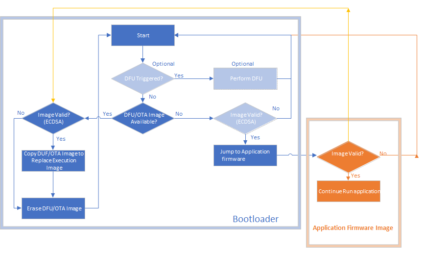
Flow Diagram of Bootloader
The detailed flow diagram of bootloader with the optional DFU block can be found below