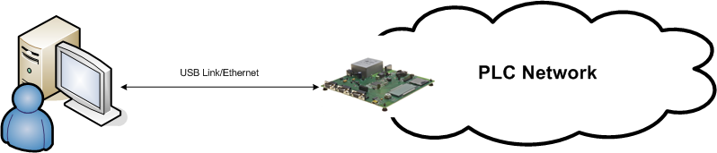
The PLC Sniffer has been developed to monitor data traffic on power line networks. This tool focuses on PRIME (versions 1.3 and 1.4) and G3-PLC standards. It requires a hardware probe device physically connected to the power line to snoop. This hardware device will send the packet sent on the network through a serial link or a TCP/IP connection to a PC host running this software. Hardware probes are passive elements inside the network. Thus, they do not interfere either physically or logically with the network.
- Analyze network problems
- Gather and report network statistics
- Monitor network usage
- Debug network protocols
- Improve network understanding
- Packet view. This is the basic presentation. It is made on the main application window and it is always visible. Each message is decoded and split in its different fields. These fields are selectively shown in the windows, in a sample per line basis. Color codes are applied depending on the packet type
- PDU view. This window displays detailed information associated with a certain message, which has been selected by the user from the message list
- Hexadecimal view. This view allows inspecting packet data in raw mode. Data is shown in hexadecimal format
- Network structure view. This view displays the logical network structure. This information is inferred analyzing in real time all the packets received from the sniffer. Selecting a packet in the Packet View will update this view accordingly. It is recommended to use this feature with a sniffer connected nearby a concentrator. This view is only available for PRIME standard
On the acquired packets, we can also apply a set of filtering rules, so we can remove unnecessary information in the samples or highlight the desired portions of them. The application of these filters does not affect the sample database, so that we can reverse their action at any time.
The PLC Sniffer stores all the acquired frames in a SQLite database. Using a SQL database allows performing of complex analysis of the data, even if the database is being updated at the same time. SQL also helps to handle the complexity of large log files.
Disclaimer
It should be kept in mind that the traffic analysis could include discrepancies with reality. Traffic seen by the hardware sniffer device may differ from what other devices on the network see due to the nature of the PLC channel. Recording information nearby the concentrator will produce the best results.
It also should be noted that the database stores the events to build the logical structure of the network. These events may or may not have a full representation of a network depending on when the sniffer has started to collect data and the point where the hardware device is connected. Best results are obtained when the sniffer session is started right after the Base Node starts operating in the network.
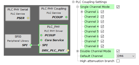
PLC Channels Configuration
The PHY Sniffer application loads by default the configuration to use all the channels available in single and double modes supported by the platform. If other coupling configuration is required, it can be easily modified in PLC_PHY module of the project graph in MPLAB Code Configurator: