2.2.4 Adding Harmony Modules to Project
- Go to MCC Project Graph window, as opened in previous step
Figure . MCC Project Graph 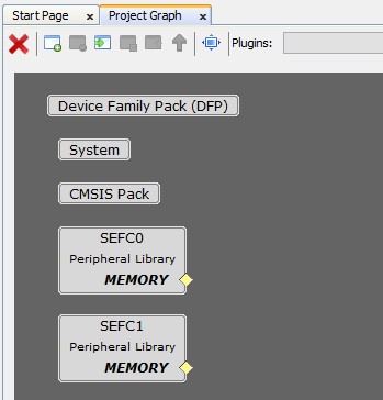
- Add BSP Component. On Device Resources, navigate to Board Support Packages (BSPs) and click on + sign next to PIC32CXMTSH Development Board BSP
Figure . Add BSP Component 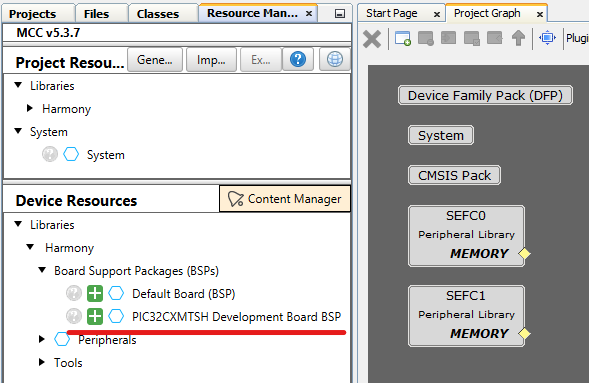
Add Core Component
- On Device Resources, navigate to Core and click on + sign next to Core
Figure . Add Core Component 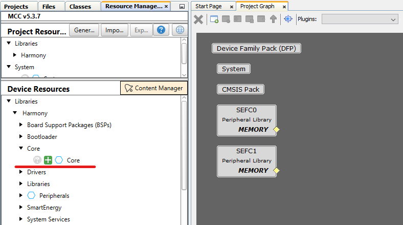
- Click No when prompted for adding FreeRTOS component. This example is a Baremetal project
Figure . Do Not Add FreeRTOS 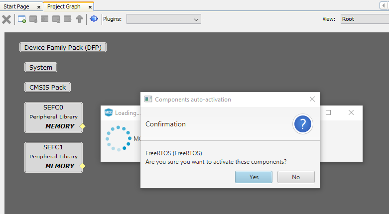
Add Time Component
- On Device Resources, navigate to System Services and click on + sign next to Time
Figure . Add Time Component 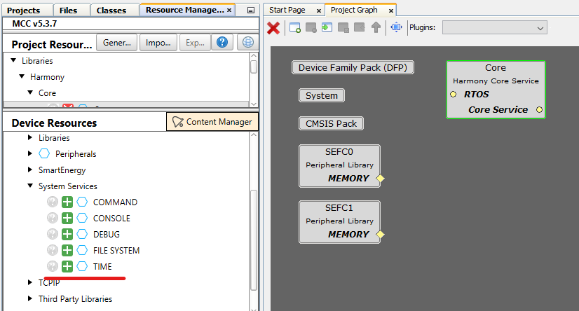
- Right-Click on TMR dependency and select Satisfiers → TC0 (tc0)
Figure . Select TC0 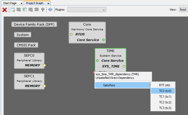
- Click on TC0 component, on Configuration Options set Clock Source to MCK0/128 on Channel 0 so configuration matches the following:
Figure . Configure TC0 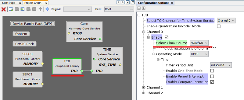
Add G3 MAC RT Component
- On Device Resources, navigate to SmartEnergy → Drivers and click on + sign next to G3 MAC RT
Figure . Add G3 MAC RT Component 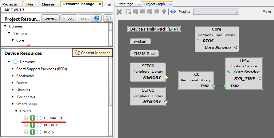
- Right-Click on SPI dependency and select Satisfiers → FLEXCOM1 (flexcom1)
Figure . Select Flexcom1 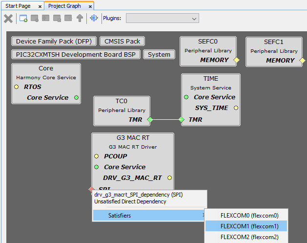
- FLEXCOM1 component is auto-configured when connected to G3 MAC RT component, as seen on the figure:
Figure . FLEXCOM1 Autoconfigured 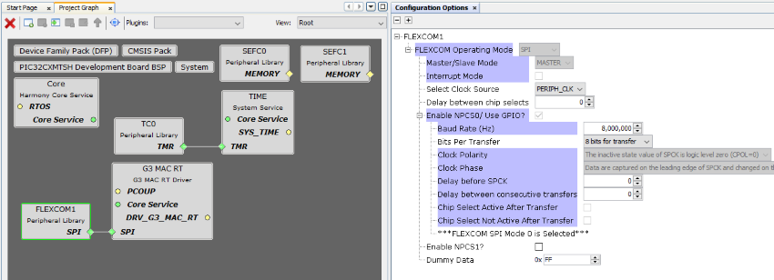
- Click on G3 MAC RT component, on Configuration Options set Pins and PLC Coupling so configuration matches the following:
Figure . Configure G3 MAC RT 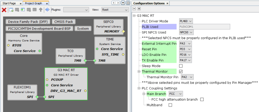
- Right-Click on PCOUP dependency and select Satisfiers → PLC PHY Coupling (srv_pcoup)
Figure . Select PHY Coupling 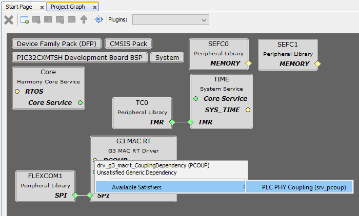
Add PLC PVDD Monitor Component
- On Device Resources, navigate to SmartEnergy → Services and click on + sign next to PLC PVDD Monitor
Figure . Add PLC PVDD Monitor Component 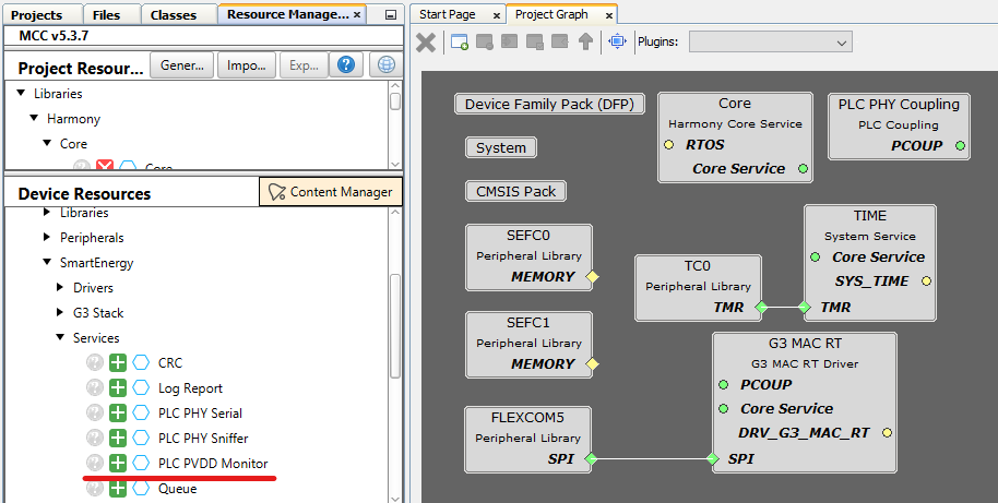
- Right-Click on ADC dependency and select Satisfiers → ADC (adc)
Figure . Select ADC 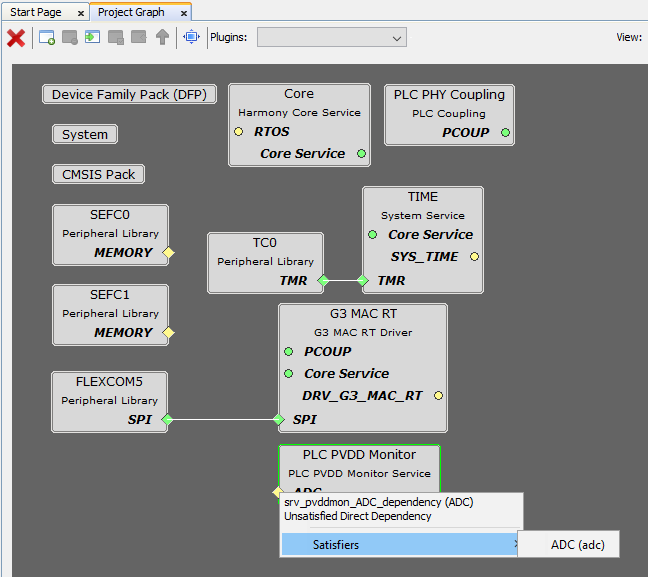
- Click on ADC component, on Configuration Options set Prescaler and Channel 1 Options so configuration matches the following:
Figure . Configure ADC 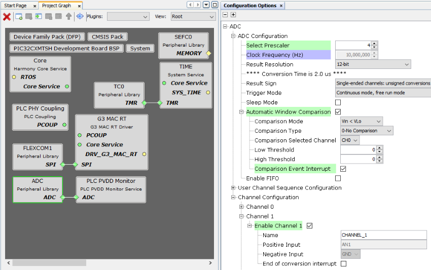
- Click on PLC PVDD Monitor component, on Configuration Options set Channel 1 so configuration matches the following:
Figure . Configure PVDD Monitor 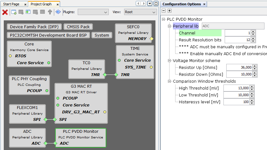
- Add TRNG Component. On Device Resources, navigate to Peripherals and click on + sign next to TRNG
Figure . Add TRNG Component 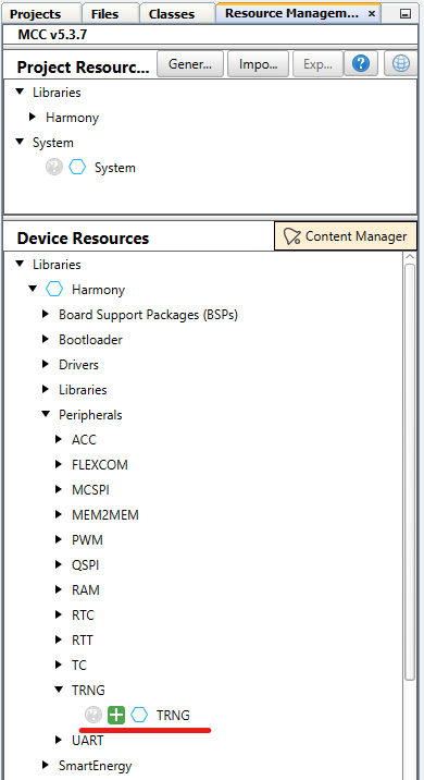
Optional. Add QSPI Memory Support if application requires using it
- On Device Resources, navigate to Drivers → I2C EEPROM and click on + sign next to MEMORY
Figure . Add Memory Component 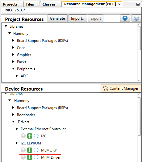
- Right-Click on MEMORY dependency and select Satisfiers → SST26 (drv_sst26)
Figure . Select SST26 Driver 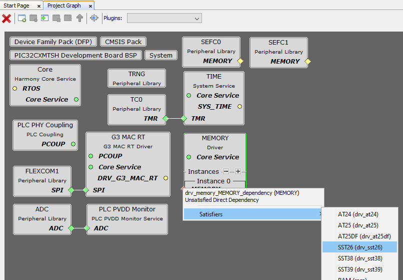
- Right-Click on SPI dependency and select Satisfiers → QSPI (qspi)
Figure . Select QSPI 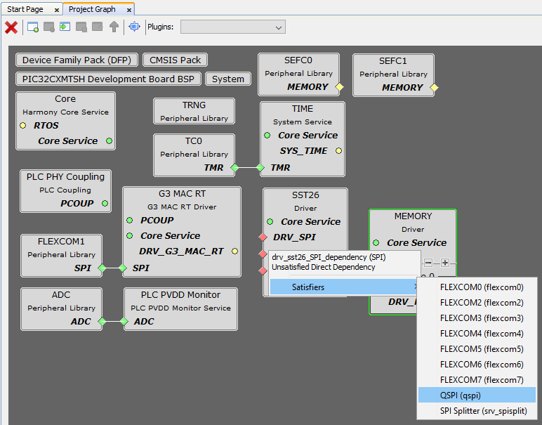
These components are Autoconfigured, once added to the project they are ready to use
Optional. Add SLCDC Display Support if application requires using it
- On Device Resources, navigate to Graphics → Driver and click on + sign next to SLCDC Driver
Figure . Add SLCD Component 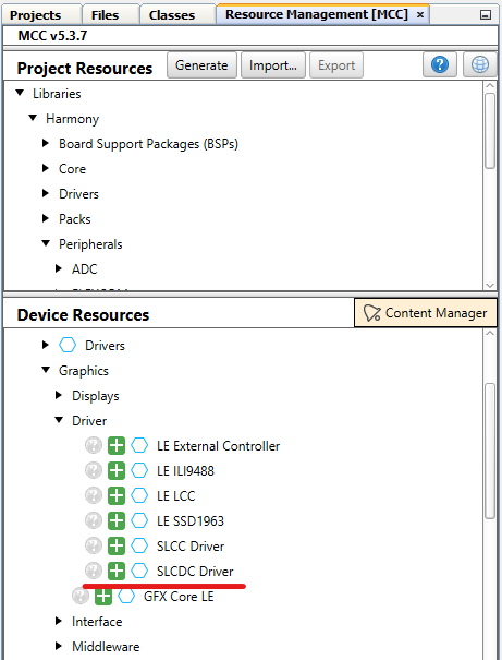
- Right-Click on Segmented Display dependency and select Satisfiers → SLCDC PIC32CXMT
Figure . Select SLCDC PIC32CXMT 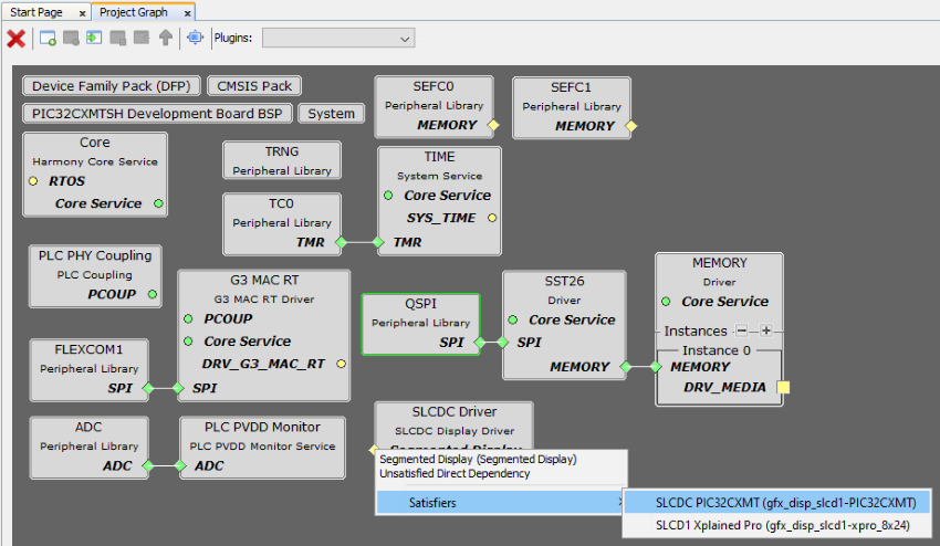
These components are Autoconfigured, once added to the project they are ready to use
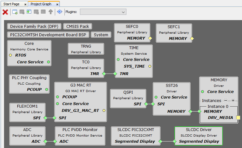
- At this point all components are added and configured in the project graph
Figure . Complete Project Graph