
The application continuously uses the graphics library to render text, fill areas, and draw images to the screen. Once a layer is completely rendered to, the graphics library increments a layer swap counter. The application periodically (at 1 second intervals) samples the layer swap counter and calculates the difference from the previous sample. This difference is shown as the Frame Update Rate (Hz).
The following diagrams show the various software and hardware blocks used by each project:
In this configuration, the Aria Graphics library renders the frame to a 32-bit frame buffer in external DDR. The LCDC display controller on the A5D2 is used to drive frame data from DDR to the display. 32-bit RGBA8888 frame buffer is stored in the external DDR memory.
User touch input on the display panel is received thru the PCAP capacitive touch controller, which sends a notification to the Touch Input Driver. The Touch Input Driver reads the touch information over I2C and sends the touch event to the Graphics Library thru the Input System Service.
• Input system service and driver
• Time system service, timer-counter peripheral library and driver
• LCDC peripheral and driver
• I2C driver
• 32-bit RGBA8888 color depth support
• RAW, RAW RLE, JPEG and PNG images stored in internal flash
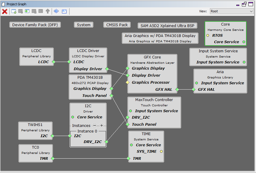
The Project Graph diagram below shows the Harmony components that are included in this application. Lines between components are drawn to satisfy components that depend on a capability that another component provides.
Adding the “SAM A5D2 XPlained Ultra BSP” and “Aria Graphics w/ PDA TM4301B Display” Graphics Template component into the project graph will automatically add the components needed for a graphics project and resolve their dependencies. It will also configure the pins needed to drive the external peripherals like the display and the touch controller.
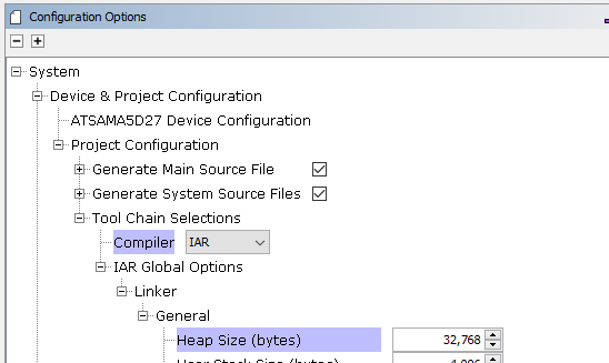
The GFX template automatically sets the heap size to 32768 bytes. The heap is set in the System component properties as shown in the image below.
The parent directory for this application is gfx_apps/apps/aria_benchmark.
The application requires the IAR Embedded Workbench to build. In the IAR workbench, open the workspace from gfx_apps/apps/aria_benchmark/firmware/aria_bm_a5d2_xu_tm4301b.IAR and build it. The build will generate a binary file harmony.bin. Copy harmony.bin to a FAT32-formatted SD card. The SD card must also contain the supplied bootloader binary needed to boot Harmony applications. Insert the card to the SDMMC1 port on the SAM A5D2 Xplained Ultra board.
To build this application, see Getting Started with Harmony 3 on SAMA5D2.
MPLAB X IDE Project Configurations
The following table lists and describes the supported configurations:
|
Project Name |
BSP Used |
Graphics Template Used |
Description |
|
aria_bm_a5d2_xu_tm4301b.IAR |
SAM A5D2 Xplained Pro |
Aria Graphics w/ PDA TM4301B Display |
Aria GFX on SAM A5D2 Xplained Ultra with PDA TM4301B 480x272 (WQVGA) Display |
 Important! Important! |
This application may contain custom code that is marked by the comments // START OF CUSTOM CODE ... and // END OF CUSTOM CODE. When using the MPLAB Harmony Configurator to regenerate the application code, use the "ALL" merging strategy and do not remove or replace the custom code. |
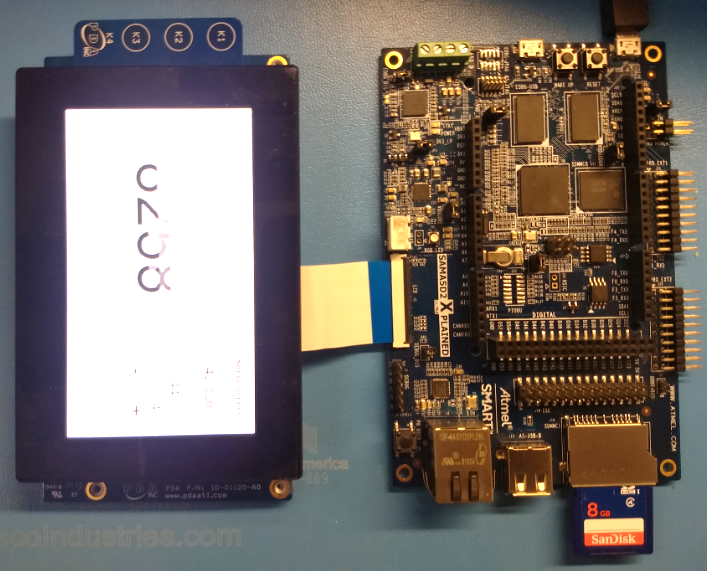
The final hardware set-up should be:
On start-up, the application will display a splash screen.
After the splash-screen completes, the String Update benchmark screen is shown. In this screen, a counter is incremented at every application cycle. The screen demonstrates the rate at which the graphics library renders a string on the screen. This involves a fill operation that clears the background, lookup of the glyphs from the string library, and the drawing of the glyphs on the frame buffer.
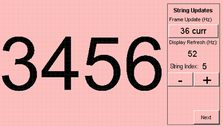
The “Frame Update (Hz)” field shows the current or instantaneous rate at which the graphics library updates the label widget that shows the counter value. Touching the Frame Update value switches between the current value (curr) and the average (avg) value across 10 samples.
Touching the “+” and “-“ buttons increases and decreases the size of the string, respectively.
Touching the “Next” button switches to the Motion and Fill benchmark screen. In this screen, squares are showing moving across the screen. The Frame Update value is the rate at which the graphics library is able to render all the squares on the screen at their new positions. This involves a fill operation of the background color at the old location of the squares and a fill of the squares’ colors at the new position.
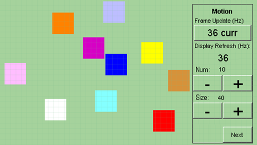
The number and size of the squares can be increased and decreased using the “+“ and “-“ buttons. If the maximum or minimum size is reached, touching “+” or “-“, respectively, will switch to a full screen fill of alternating colors.
Touching the “Next” button transitions to the Image Decode and Rendering screen. In this screen, two images of the same size are alternately rendered between application cycles. This involves a fill of the background color, decode and conversion of the image to the frame buffer format, and the drawing of the image to the frame buffer. The Frame Update value is the rate at which the graphics library is able to render an image on the screen.
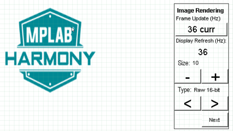
The size of the images can be increased and decreased using the “+“ and “-“ buttons.
Touching the “<” and “>” buttons switches between the various image formats. The formats that are supported are PNG, RAW RLE 16-bit, RAW 16-bit and JPG 24-bit. RAW 32-bit pre-decoded in DDR is also supported in the PIC32MZ DA configurations with DDR memory
|
MPLAB® Harmony Graphics Suite Applications
|