The application uses the aria graphics library to render text on a label widget, an image and a user-interactive button to the screen. Touching the button on the screen will show the button being pressed.
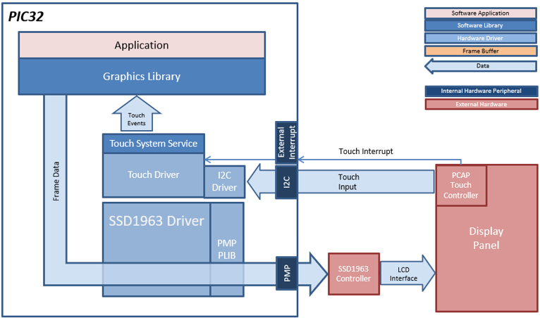
The block diagram(s) below show(s) the various software and hardware blocks used in this application:
The SSD1963 display controller is used to send the display data and timing to a display. The SSD1963 is connected to the PIC32MZ EF thru the EBI peripheral and GPIOs which are used to send 16-bit parallel data/commands and control signals to the SSD1963 controller. The frame buffer is stored externally in the SSD1963 controller.
User touch input on the display panel is received thru the PCAP capacitive touch controller, which sends a notification to the Touch Input Driver. The Touch Input Driver reads the touch information over I2C and sends the touch event to the Graphics Library thru the Input System Service.
• Aria Graphics Library
• Input system service and touch driver
• Time system service, timer-counter peripheral library and driver
• SSD1963 display controller driver
• 16-bit RGB565 color depth support (65535 unique colors)
• EBI peripheral library and driver
• I2C peripheral library and driver
• Uncompressed RAW images color depth-matched (16-bit RGB565) stored in internal flash
• Fast NVM-to-Frame Buffer rendering using image direct blit feature

The Project Graph diagram below shows the Harmony components that are included in this application. Lines between components are drawn to satisfy components that depend on a capability that another component provides.
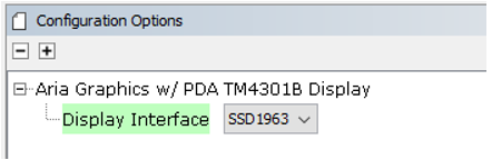
Adding the “PIC32MZ EF Curiosity 2.0 BSP” and “Aria Graphics w/ PDA TM5000 Display” Graphics Template component into the project graph. The template will need to be configured for SSD1963 interface by selecting SSD1963 for the Display Interface option.
This will automatically add the components needed for a graphics project and resolve their dependencies. It will also configure the pins needed to drive the external peripherals like the display and the touch controller.
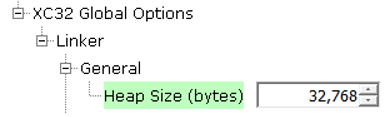
To ensure there is sufficient heap memory for the Aria Graphics Library widget creation and screen transitions, the Heap Size is increased to 32768.
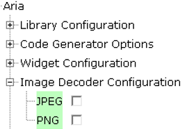
Since all the images in this demonstration are uncompressed, the code space takes up the majority of the 2MB flash space on the MZ EF processor. To save as much flash as possible, JPEG and PNG decoders are disabled.
The parent directory for this application is gfx_apps/apps/aria_thermostat. To build this application, use MPLABX to open the gfx_apps/apps/aria_thermostat/firmware/aria_th_mzef_cu_tm5000_ssd1963.X project file.
The following table lists configuration properties:
|
Project Name |
BSP Used |
Graphics Template Used |
Description |
|
aria_th_mzef_cu_tm5000_ssd1963.X |
PIC32MZ EF Curiosity 2.0 |
Aria Graphics w/ PDA TM5000 Display |
PIC32MZ EF Curiosity 2.0 with SSD1963 GFX Interface and 5” WVGA PCAP Touch display |
Note: This application may contain custom code that is marked by the comments "// START OF CUSTOM CODE ..." and "// END OF CUSTOM CODE". If you use the MPLAB Harmony Configurator to regenerate the application code, do not remove or replace the custom code.
This section describes how to configure the supported hardware.
Description
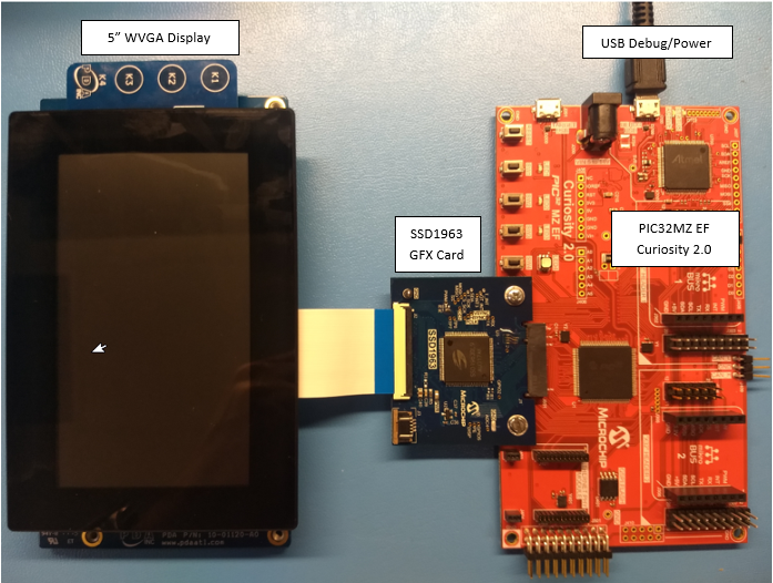
Configure the hardware as follows:
• Attach the SSD1963 GFX Interface Card to the J601 connector on the PIC32MZ EF Curiosity 2.0 board.
• Connect the ribbon cable from the WVGA display to the J2 connector on the SSD1963 GFX Interface card.
• Connect a USB cable from the host computer to the DEBUG USB port on the PIC32MZ EF Curiosity 2.0 board. This USB connection is used for power, code download and debugging.
The final hardware setup should be:
This section provides information on how to run and use the application.

After the completion of the Splash Screen, the display black light will fade thee screen black as it transitions to the Main Screen.
The main screen will display a modern thermostat design:
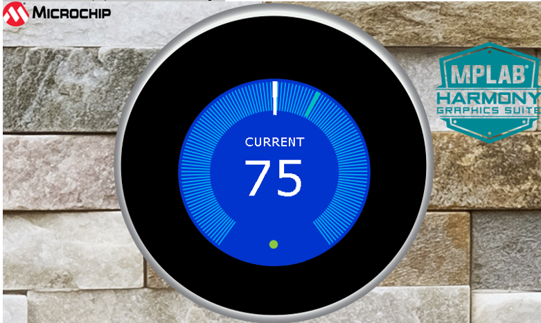
Touch any of the circular part of the thermostat UI highlighted by the cyan blue lines will move the white needle on the gauge. This simulates a user setting the temperature on the device. Once released, the UI will display changing temperatures as it simulates an HVAC system heating/cooling the room to the temperature set by the user.
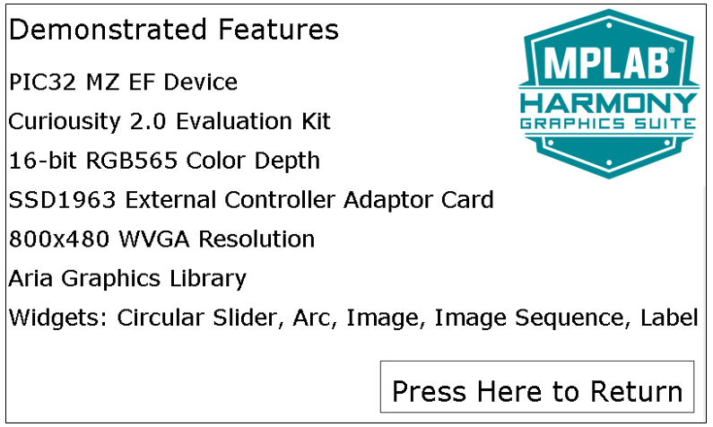
Touch either the MPLAB Harmony Graphics Suite logo or the Microchip logo on the screen will change the change to the Information Screen.
The information screen serves as a screen to list out the demonstrated features of the demo. Touching “Press Here to Return” will bring the application back to the Main Screen.
|
MPLAB® Harmony Graphics Suite Applications
|