![]()
AC Sleepwalking
This example application shows how to use the AC Peripheral library to perform a single shot comparison in standby sleep mode periodically and wake up the device at the end of a successful comparison.
Description
Single shot conversion is triggered by RTC compare event. Generation of a trigger and compare operation are done while the CPU is in the standby sleep mode. AC generates the interrupt on the end of the comparison which wakes the CPU.
Downloading and building the application
To clone or download this application from Github, go to the main page of this repository and then click Clone button to clone this repository or download as zip file. This content can also be downloaded using content manager by following these instructions.
Path of the application within the repository is apps/ac/ac_sleepwalk_singleshot/firmware .
To build the application, refer to the following table and open the project using its IDE.
| Project Name | Description |
|---|---|
| sam_d21_xpro.X | MPLABX project for SAM D21 Xplained Pro Evaluation Kit |
| sam_da1_xpro.X | MPLABX project for SAM DA1 Xplained Pro Evaluation Kit |
Setting up the hardware
The following table shows the target hardware for the application projects.
| Project Name | Board |
|---|---|
| sam_d21_xpro.X | SAM D21 Xplained Pro Evaluation Kit |
| sam_da1_xpro.X | SAM DA1 Xplained Pro Evaluation Kit |
Setting up SAM D21 Xplained Pro Evaluation Kit
- Connect a voltage below VDD to pin 17 of the EXT1 connector
- Connect the Debug USB port on the board to the computer using a micro USB cable
Setting up SAM DA1 Xplained Pro Evaluation Kit
- Connect a voltage below VDD to pin 17 of the EXT1 connector
- Connect the Debug USB port on the board to the computer using a micro USB cable
Running the Application
- Open the Terminal application (Ex.:Tera term) on the computer
- Connect to the EDBG Virtual COM port and configure the serial settings as follows:
- Baud : 115200
- Data : 8 Bits
- Parity : None
- Stop : 1 Bit
- Flow Control : None
- Build and Program the application using its IDE
-
Observe output message in console as follows:
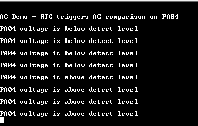
- Console displays the message stating whether voltage at AC input is lower or greater than the internal bandgap voltage (1.1 V)
- LED toggles when comparison is done
Below table shows the AC input pin and LED name for the board
| Board | AC input pin | LED name |
|---|---|---|
| SAM D21 Xplained Pro Evaluation Kit | pin 17 of the EXT1 connector | LED0 |
| SAM DA1 Xplained Pro Evaluation Kit | pin 17 of the EXT1 connector | LED0 |