![]()
SDADC Sample
This example application shows how to sample an analog input using SDADC and displays the converted samples on a serial terminal.
Description
In this application, the DAC output is fed to an analog input for the SDADC conversion. An analog input is converted by a software trigger and the converted value is displayed on the console. DAC output is changed by 0.1 V upon switch press. The SDADC sample output is between 0.0 V to 3.3 V and it starts from 1.65 V when device is reset.
Downloading and building the application
To clone or download this application from Github, go to the main page of this repository and then click Clone button to clone this repository or download as zip file. This content can also be downloaded using content manager by following these instructions.
Path of the application within the repository is apps/sdadc/sdadc_sample/firmware .
To build the application, refer to the following table and open the project using its IDE.
| Project Name | Description |
|---|---|
| sam_c21n_xpro.X | MPLABX project for SAMC21N Xplained Pro Evaluation Kit |
Setting up the hardware
The following table shows the target hardware for the application projects.
| Project Name | Board |
|---|---|
| sam_c21n_xpro.X | SAMC21N Xplained Pro Evaluation Kit |
Setting up SAMC21N Xplained Pro Evaluation Kit
- Analog input (AIN1) of SDADC is fed from the DAC output.
- SDADC “INP1” is mapped to Port Pin “PB09”, and is routed to “Pin 3 of the EXT1 header”
- SDADC “INN1” is mapped to Port Pin “PB08”, and is routed to “Pin4 of the EXT1 header”
- DAC output is available between Port Pin “PA02” and GND pin and these are routed to “Pin 1 and Pin 2 of the DAC header”
- Use the jumper wires to connect below pins:
- “Pin 3 of the EXT1 header” to “Pin 1 of the DAC header”
- “Pin 4 of the EXT1 header” to “Pin 2 of the DAC header”
- Connect the Debug USB port on the board to the computer using a micro USB cable
Running the Application
- Open the Terminal application (Ex.:Tera term) on the computer
- Connect to the EDBG Virtual COM port and configure the serial settings as follows:
- Baud : 115200
- Data : 8 Bits
- Parity : None
- Stop : 1 Bit
- Flow Control : None
- Build and Program the application project using its IDE
- The console displays the converted digital value
- Press the switch to change the DAC value by 0.1 V and observe the changed SDADC value on the console
Refer to the table below for details of the switch used:
| Board | Switch |
|---|---|
| SAMC21N Xplained Pro Evaluation Kit | SW0 |
-
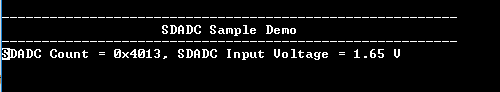
Console displays the SDADC count and the SDADC input voltage in the console as shown below: