![]()
USART driver asynchronous - USART multi instance
This example echoes the received characters over the two consoles using the USART driver in asynchronous mode.
Description
This example uses the USART driver in asynchronous mode in both Bare-Metal and RTOS environments to communicate over two consoles. It receives and echoes back the characters entered by the user on the respective console.
Downloading and building the application
To clone or download this application from Github, go to the main page of this repository and then click Clone button to clone this repository or download as zip file. This content can also be downloaded using content manager by following these instructions.
Path of the application within the repository is apps/driver/usart/async/usart_multi_instance/firmware .
To build the application, refer to the following table and open the project using its IDE.
| Project Name | Description |
|---|---|
| sam_a5d2_xult.X | MPLABX project for SAMA5D2 Xplained Ultra Evaluation Kit |
| sam_a5d2_xult_freertos.X | MPLABX project for SAMA5D2 Xplained Ultra Evaluation Kit |
Setting up AT91Bootstrap loader
To load the application binary onto the target device, we need to use at91bootstrap loader. Refer to the at91bootstrap loader documentation for details on how to configure, build and run bootstrap loader project and use it to bootstrap the application binaries.
Setting up the hardware
The following table shows the target hardware for the application projects.
| Project Name | Board |
|---|---|
| sam_a5d2_xult.X sam_a5d2_xult_freertos.X | SAMA5D2 Xplained Ultra Evaluation Kit |
Setting up SAMA5D2 Xplained Ultra Evaluation Kit
Addtional hardware required
- USB UART CLICK board
Setting up the board
-
Connect USB UART CLICK board to the evaluation kit using the pin connections described below:
SAM A5D2 Xplained Ultra board Pins USB UART Click board Pins F0_TXD, J22 connector RX F0_RXD, J22 connector TX PIN 20, XPRO EXT2 connector 3.3V PIN 19, XPRO EXT2 connector GND - Short jumper JP2 (DEBUG_DIS)
- Connect the Debug USB port on the board to the computer using a micro USB cable
Running the Application
- Build the application using its IDE
- Open the Terminal application (Ex.:Tera term) on the computer for both ports
- Connect to the EDBG/Jlink Virtual COM port and configure the serial settings as follows:
- Baud : 115200
- Data : 8 Bits
- Parity : None
- Stop : 1 Bit
- Flow Control : None
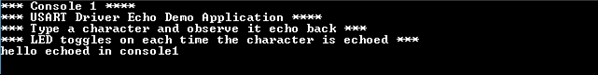
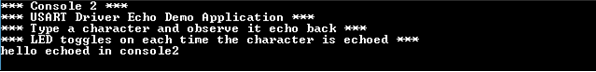
- Type a character and observe the output on the two consoles as shown below:
- If success the character typed echoes back and an LED toggles on each time the character is echoed
- Console 1
- Console 2
Refer to the following table for LED name:
| Board | LED Name |
|---|---|
| SAMA5D2 Xplained Ultra Evaluation Kit | RGB_LED(Green) |