This is the diagram that appears in the PRIME specification 1.3.6 showing the disconnection process initiated by a Base Node. It shows how the base node sends a disconnection request to the Service Node via another switch.

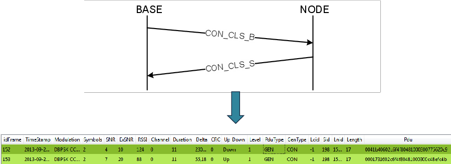
The sniffer capture shown below shows the disconnection process initiated by a Base Node but in this case, there is not any intermediate switch, so there are only 2 devices involved: the Base Node and the terminal or Service Node. The next image shows the disconnection process with the 2 frames involved:
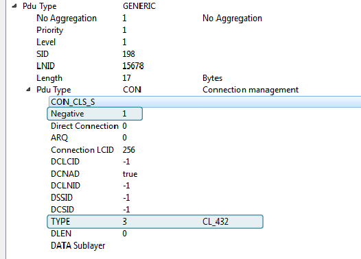
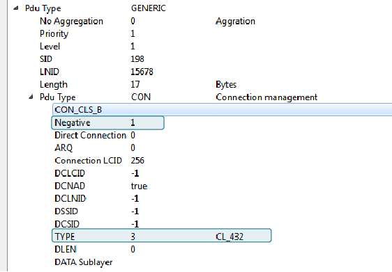
In order to obtain more details, if you go to the packet view, it is possible to find the type of messages and associate them with the previous diagram (In this case is a 4-32 connection):
- Frame 152:
- Frame 153: