 legato_qs_mzda_round.X
Defining the Architecture
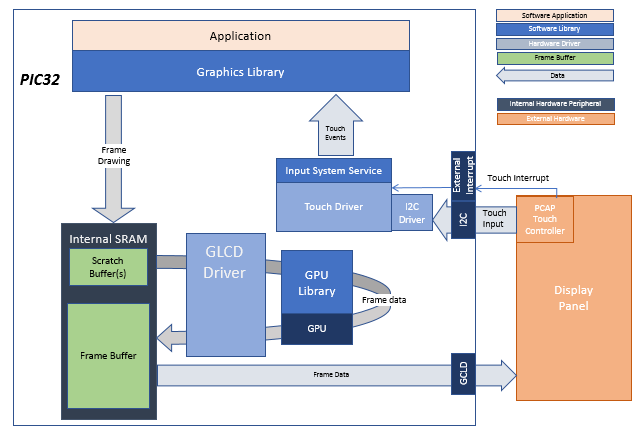
The demo showcases a Smart Home Control User Interface on a stylish, round form factor display. Multiple control user interfaces for common home appliance and utilities like thermostat, fans and lighting can be launched from the main menu screen. The demo utilizes the round touch screen display and rotary knob to allow touch and wheel input that complements the round screen and user interface.
Demonstration Features
- Legato Graphics Library
- Multiple interactive and touch-enabled appliance and utility control user interfaces
- Signature application for the PIC32MZ DAR/DAS devices with Internal DDR and round display
- 24-bit color, multi-layer, circular display (432x432) screen design
- Graphics Acceleration using integrated display controller (GLCD)
Creating the Project Graph

Adding the PIC32MZ DA Radial Board BSP and Legato Graphics w/ LCF0300633GGU00 Display Graphics Template component into the project graph will automatically add the components needed for a graphics project and resolve their dependencies. It will also configure the pins needed to drive the external peripherals like the display.
Building the Application
The parent directory for this application is gfx/apps/legato_quickstart_round. To build this application, use MPLAB X IDE to open the gfx_apps/apps/legato_quickstart/firmware/legato\qs_mzda_round.X project file.
The following table lists configuration properties:
| Project Name | BSP Used | Graphics Template Used | Description |
|---|---|---|---|
| legato_qs_mzda_round_X | PIC32MZ DA Radial Board | Legato Graphics w/ LCF0300633GGU00 Display | PIC32MZ DA Radial Graphics Development Board (RGDB) w/ LCF0300633GGU00 Display |
Configuring the Hardware
The final setup should be:
Configure the hardware as follows:
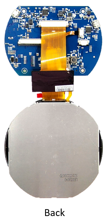
- Attach the LCD and touch cable from the LCD module to the board.
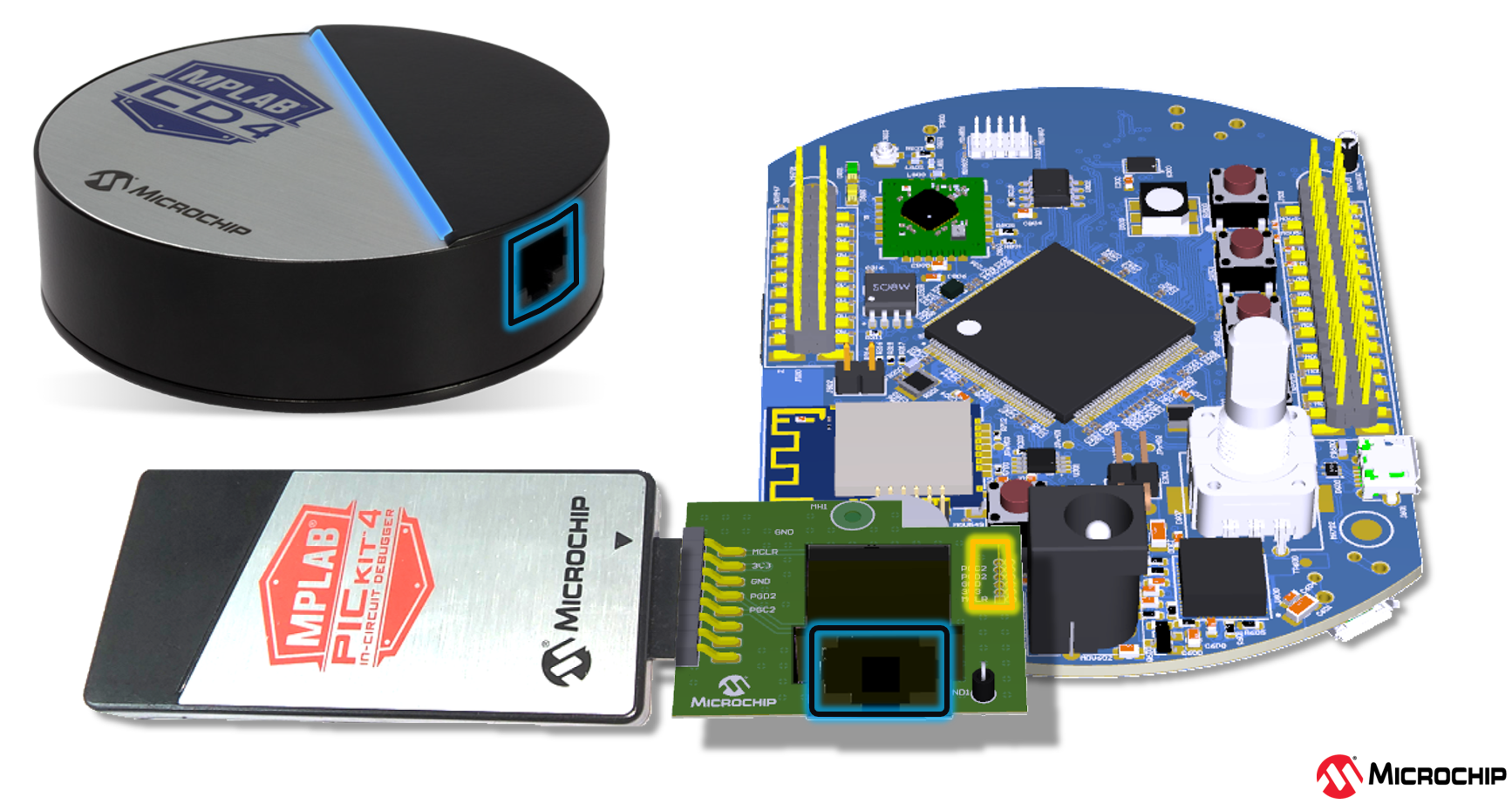
- An external debugger like ICD4 or PICKit4 is needed to debug and program the board. To connect a debugger, the ICSP Adapter board must be connected to the RGDB board and the debugger must be connected to the ICSP Adapter Board. The ICSP Adapter board header J2 connects to ICSP header J300 of the RGDB, as shown below.
- Refer to the RGDB User’s Guide for more details.
The final hardware setup should similar to the image below:

Running the Demonstration
The demo boots to the quickstart screen.

Touching the “Quick Start” button will toggle the button.
